Bose 321 Owner's guide - Page 14
On the Acoustimass, VIDEO OUTPUT - cables
 |
UPC - 017817493475
View all Bose 321 manuals
Add to My Manuals
Save this manual to your list of manuals |
Page 14 highlights
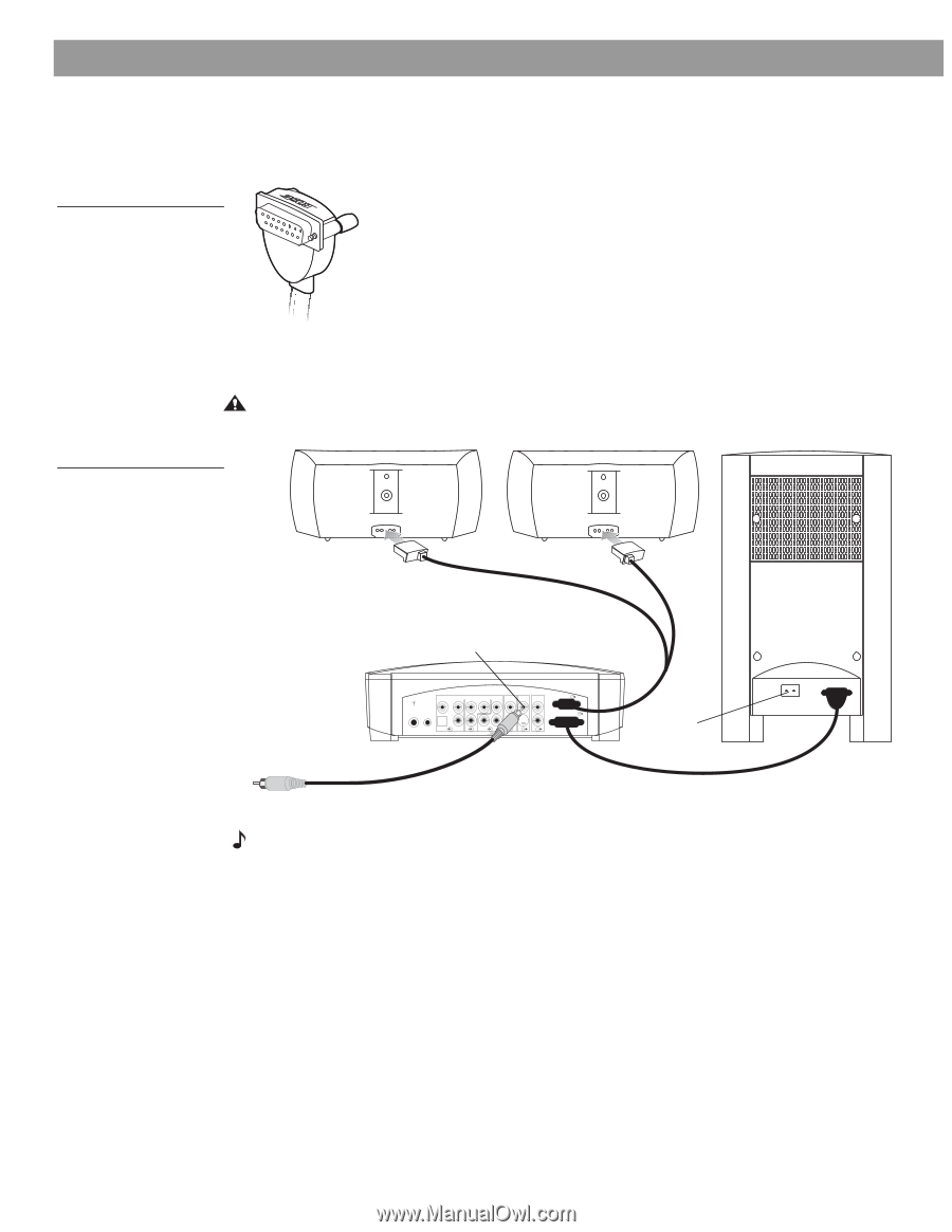
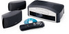
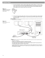
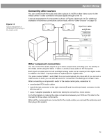
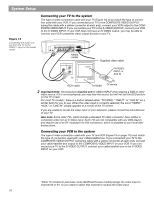
System Setup Figure 11 Right-angle connector that attaches to the Acoustimass module 4. On the Acoustimass® module, insert the right-angle connector (Figure 11) of the Acoustimass module cable into the jack labeled MEDIA CENTER. On the rear panel of the media center, insert the other end of the cable into the jack labeled ACOUSTIMASS MODULE. Firmly tighten the two screws at each end of the cable. Figure 12 Basic connections to the media center 5. On the rear panel of the media center, insert one end of the supplied video cable (marked in yellow) to VIDEO OUTPUT (Figure 12). Insert the other end of the cable into the video input on your TV. CAUTION: Do not plug the Acoustimass module into an AC power (mains) outlet until all the components are connected. RIGHT LEFT To TV video input VIDEO OUTPUT Speaker cable VIDEO D L 75 Ω FM AM LOOP ANTENNA ANTENNA OPTICAL R AUDIO INPUT IDEO 2 L D R D AUX L VIDEO INPUT C VIDEO OUTPUT C AUDIO OUTPUT L SPEAKERS R S ACOUSTIMASS MODULE S R AC input jack AC INPUT MUSIC CENTER Acoustimass module cable Note: Before using your TV to play a DVD or other video source, be sure to read the Important Note on page 16. S-video as an alternate means to connect to the TV An S-video input jack, provided on many TVs, delivers a higher-quality TV picture than the composite video output connection shown above. To make this alternate connection, insert the end of an S-video cable from the TV into the SVIDEO OUTPUT on the media center. This cable may be purchased from your Bose® dealer or a local electronics retailer. 14 AM256950_02_V.pdf • January 29, 2002
-
 1
1 -
2
-
3
-
4
-
5
-
6
-
7
-
8
-
 9
9 -
 10
10 -
 11
11 -
 12
12 -
 13
13 -
 14
14 -
 15
15 -
 16
16 -
 17
17 -
 18
18 -
 19
19 -
20
-
21
-
22
-
23
-
24
-
25
-
26
-
27
-
28
-
29
-
30
-
31
-
32
-
33
-
34
-
35
-
36
-
37
-
38
-
39
-
40
-
41
-
42
-
43
-
44
 |
 |