Bose 321 Owner's guide - Page 17
Attaching the supplied antennas, FM antenna - speaker cable
 |
UPC - 017817493475
View all Bose 321 manuals
Add to My Manuals
Save this manual to your list of manuals |
Page 17 highlights
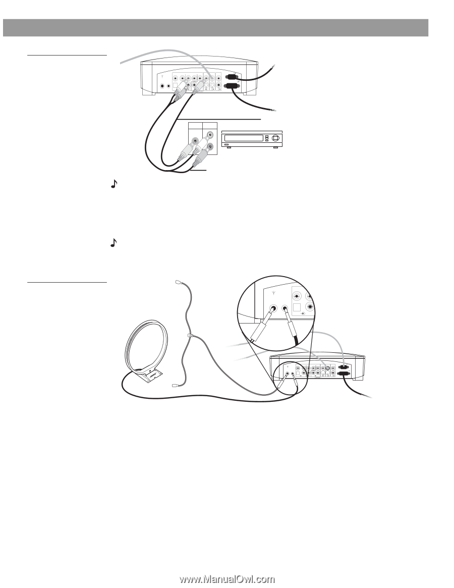
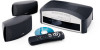
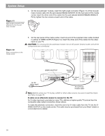
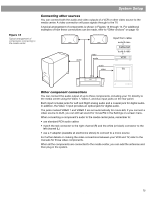
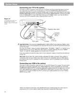
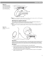
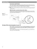
System Setup Figure 15 Connecting audio output from a VCR to the VIDEO 2 input on the media center, and the video from the VCR to the composite video input on the media center Figure 16 Adding the AM and FM antennas VIDEO 1 D L 75 Ω AM FM LOOP ANTENNA ANTENNA OPTICAL R AUDIO INPUT VIDEO 2 L D R D AUX L VIDEO INPUT C VIDEO AUDIO OUTPUT OUTPUT C L SPEAKERS R S ACOUSTIMASS MODULE S R Media center VIDEO OUT AUDIO OUT Video cable L R VCR RCA cable Note: Do not connect the video output of your 3•2•1 system media center to a VCR; playing copy-protected DVDs may result in poor picture quality. Attaching the supplied antennas The rear panel of the media center provides jacks for AM and FM antennas (Figure 16). Unwind the wires of each antenna to ensure the best reception. Note: An outdoor antenna may be used in place of the two that are supplied. To add an outdoor antenna, consult a qualified installer. Follow all safety instructions supplied with the antenna. A VIDEO D L 75 Ω FM AM LOOP ANTENNA ANTENNA OPTICAL R FM AM VIDEO D L 75 Ω FM AM LOOP ANTENNA ANTENNA OPTICAL R AUDIO INPUT IDEO 2 L D R D AUX L VIDEO INPUT C VIDEO AUDIO OUTPUT OUTPUT C L SPEAKERS R S S R ACOUSTIMASS MODULE FM antenna Plug the connector into the FM antenna jack on the media center rear panel. Spread out the antenna arms at the other end and move them around to establish optimum FM reception. Extend the antenna as far from the media center and other external equipment as possible. AM antenna 1. Plug the connector into the AM antenna jack on the media center. 2. Move the antenna loop as far as possible, at least 20 inches (50 centimeters) from the media center and at least 4 feet (1.2 meters) from the Acoustimass® module. Experiment with positioning the loop for optimum AM reception. 3. Follow the instructions enclosed with the AM loop antenna to stand it on the supplied base, or mount it to a wall. AM256950_02_V.pdf • January 29, 2002 17
-
 1
1 -
2
-
3
-
4
-
5
-
6
-
7
-
8
-
9
-
10
-
11
-
 12
12 -
 13
13 -
 14
14 -
 15
15 -
 16
16 -
 17
17 -
 18
18 -
 19
19 -
 20
20 -
 21
21 -
 22
22 -
23
-
24
-
25
-
26
-
27
-
28
-
29
-
30
-
31
-
32
-
33
-
34
-
35
-
36
-
37
-
38
-
39
-
40
-
41
-
42
-
43
-
44
 |
 |