Bose Acoustimass 700 Owner's guide
Bose Acoustimass 700 Manual
 |
View all Bose Acoustimass 700 manuals
Add to My Manuals
Save this manual to your list of manuals |
Bose Acoustimass 700 manual content summary:
- Bose Acoustimass 700 | Owner's guide - Page 1
Bose Acoustimass' 700 Home Theater Speaker System Owner's Guide __SEISE" • • - Bose Acoustimass 700 | Owner's guide - Page 2
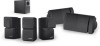
Introduction Thank you Thank you for choosing the Bose' Acoustimass* 700 home theater speaker system. It includes five speakers and an Acoustimass module, brackets for the surround speakers, speaker cable, and protective rubber feet. This package is designed for use with audio for video (AN) - Bose Acoustimass 700 | Owner's guide - Page 3
Your Acoustimass 700 speakers For realistic home theater sound Setting your Dolby Pro-Logic receiver Setting your Dolby Digital (AC-3) receiver Bass and treble adjustments Maintaining Your Acoustimass 700 speakers How to clean your speakers Troubleshooting problems • Customer Service Product - Bose Acoustimass 700 | Owner's guide - Page 4
" preceding a TV broadcast. Your Acoustimass" 700 home theater speakers are also compatible with Dolby Digital Bose dealer immediately. Note: Nowis a good time to record the serialnumber and the date ofmanufacture (DOM) on page 2 of this guide and on your warranty card. WARNING: The Acoustimass - Bose Acoustimass 700 | Owner's guide - Page 5
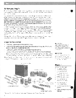
Setting Up Placing your Acoustimass" 700 speakers to achieve (realistic home theater sound Bose designed your Acoustimass 700 home theater speakers to provide high performance and flexibility. The identical cube speaker arrays are magnetically shielded, allowing you to place them near a TV screen - Bose Acoustimass 700 | Owner's guide - Page 6
The cables provided with your Acoustimass- 700 system allow for the following distances between components: • Up to 20 feet (6 m) between the Acoustimass module and the receiver • Up to 20 feet (6 m) between the Acoustimass module and the front and center cube speaker arrays • Up to 50 feet (15 - Bose Acoustimass 700 | Owner's guide - Page 7
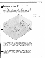
allows for room to tighten the bracket screw using a screw driver. Note: Refer to the bracket instructions in the Appendix before mounting and connecting the speakers. If you stand the speakers vertically or horizontally without using brackets, apply the rubber feet to the bottom surface of each - Bose Acoustimass 700 | Owner's guide - Page 8
module is standing on the end that has the cable connections. Figure 7 Acoustimass module positions C 0 • Connect the speakers Use the supplied 20-foot speaker cables to connect the cube speakers to the Acoustimass module and the module to your receiver. Use the 50-foot cables to connect - Bose Acoustimass 700 | Owner's guide - Page 9
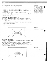
tab down and insert the ppropriate wire into the exposed hole (Figure 8). 1. Connect one end of a 20-foot cable to the right cube speaker. 2. Connect the other end to the RIGHT OUTPUT TO CUBE SPEAKERS terminals on the Acoustimasse module (see Figure 10 on page 11). 3. Repeat to connect the left cube - Bose Acoustimass 700 | Owner's guide - Page 10
to negative (in phase). Out of phase wiring can cause total loss of Acoustimass module output. Your receiver may have more than one pair of front speaker outputs. They are usually labeled Speakers A and Speakers B. Use either set of outputs unless one is designated for a particular ohm rating - Bose Acoustimass 700 | Owner's guide - Page 11
speaker ca. Center speaker Front speaker Setting Up Figure 10 Completed Acoustimase 700 speaker connections Acoustimass' module Front speaker • outputs Center and surround speaker outputs PK PrA EA SV ,.tr A 1 71O el Surround sound receiver Surround speaker 3 1/ Surround speaker - Bose Acoustimass 700 | Owner's guide - Page 12
YourAcoustinuass -700*ms/ceps For realistic home theater sound Each speaker produces only the sound directed to it by the steering logic in your AN component. For example, right front channel sound is reproduced by the speaker connected to the RIGHT FRONT SPEAKER outputs of an AN receiver. Notice - Bose Acoustimass 700 | Owner's guide - Page 13
Using Your Acoustimasse 700 Speakers Setting yourDolbyDigital(AC-3)receiver Your Acoustimass' 700 speakers are compatible with the output from Dolby Digital (AC-3) receivers. Take special care to set the channel output according to the specifications listed in the chart below. Proper size settings - Bose Acoustimass 700 | Owner's guide - Page 14
the grille cloth. No other regular maintenance is required. Troubleshooting problems If you have a problem with your Acoustimass 700 speakers, turn off your sound source and try the solutions below. Problem What to do No sound from any speakers • Make sure the receiver is plugged in and - Bose Acoustimass 700 | Owner's guide - Page 15
electronic equipment in the room to see if noise stops. • Check the receiver owner's manual for the recommended distance between it and other electronics. Customer Service oFor additional help in solving problems, contact Bose". See the inside back cover for Bose offices and phone numbers. 15 - Bose Acoustimass 700 | Owner's guide - Page 16
2 of this guide). Then address the card, detach, and mail to Bose. Technical information Features • Virtually Invisible' speaker design • Direct/Reflecting" speaker technology • Acoustimass speaker technology • One set of mounting brackets included • Automatic system protection circuitry • Syncorrr - Bose Acoustimass 700 | Owner's guide - Page 17
4 1/4 (6mm) Appendix - • -1 I 9/164 (13mm) 1/8- (3 mm) 1/4. (6 mm) yr Optional speaker cord pilot hole MIRSANaSti rldt- CAUTION: Do not mount on surfaces that are not sturdy enough, or that have hazards installer. r ote: See owner's guide section on proper placement and wiring instructions. - Bose Acoustimass 700 | Owner's guide - Page 18
Appendix Mount horizontally or vertically, with the speaker cord in the wall or along the wall. '4 O t or ii (4) • 010 x 1 1," #10 x 40 mm (4) #10 8 (4) • #10-24 x 3" (M5 x 75 mm) e (4) '4-20 x • - Bose Acoustimass 700 | Owner's guide - Page 19
i 0 Ile(3rrm) 9 14/ "(6rrm) Wood wall 41= t .-1:11id (36=1) 11,4"(6 mm) =4( Masonry wall O / M r. (1243 rim} , V( u -(7' • (Om) - -, • - 02-13 win) Wallboard wall 111 - Bose Acoustimass 700 | Owner's guide - Page 20
Appendix 0 Note: For a bracket in vertical position, you must mount "A" with the • hole for "C" at the bottom. Be sure to tighten all screws. I • Loosen screw slightly, adjust angle, re•tighten the screw. • iv - Bose Acoustimass 700 | Owner's guide - Page 21
W-16, Greater Kailash-II New Delhi 110 048 TEL (011) 648 4462 FAX (011) 648 4463 •+eland Bose Corporation Carrickmacross, Co Monaghan TEL 042-61988 FAX 042-61998 From other locations Bose Product Support, 1 New York Ave. Framingham, MA 01701-9168 USA TEL (508) 766-1900 FAX (508) 766-1919 World - Bose Acoustimass 700 | Owner's guide - Page 22
'.7 ed. • •*--. A.rt, . •• • kalis c 2Lgigei-••34, ab,••Mr:- ••-zw" - - yg reg.e.•t;" a • • . . 1 1/1 • P i l l • - t'a".t.ge'..4••• mm tI O1998 Bose Corporation, The Mountain, Framingham, MA 01701-9168 USA JN99219 PN197898 Rev.01 AM197898 Rev.01 nor Better sound through research.
-
 1
1 -
 2
2 -
 3
3 -
 4
4 -
 5
5 -
 6
6 -
 7
7 -
8
-
9
-
10
-
11
-
12
-
13
-
14
-
15
-
16
-
17
-
18
-
19
-
20
-
21
-
22
 |
 |
Bose
Acoustimass'
700
Home
Theater
Speaker
System
Owner's
Guide
__SEISE"
•
•