Brother International BAS-375E Instruction Manual - English
Brother International BAS-375E Manual
 |
View all Brother International BAS-375E manuals
Add to My Manuals
Save this manual to your list of manuals |
Brother International BAS-375E manual content summary:
- Brother International BAS-375E | Instruction Manual - English - Page 1
BAS-364E,366E INSTRUCTION MANUAL BAS-370E,375E Please read this manual before using the machine. Please keep this manual within easy reach for quick reference. PROGRAMMABLE ELECTRONIC PATTERN SEWER - Brother International BAS-375E | Instruction Manual - English - Page 2
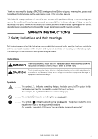
and correct operation before operating the machine so that you will know how to use the machine correctly. SAFETY INSTRUCTIONS z Safety indications and their meanings This instruction manual and the indications and symbols that are used on the machine itself are provided in order to ensure safe - Brother International BAS-375E | Instruction Manual - English - Page 3
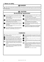
may occur. The ambient temperature should be within the range of 5°C to 35°C during use. Temperatures which are lower or higher than this may cause problems with correct operation. The relative humidity should be within the range of 45% to 85% during use, and no dew formation should occur in any - Brother International BAS-375E | Instruction Manual - English - Page 4
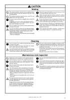
removed, be absolutely sure to re-install them to their original positions and check that they operate correctly before using the machine. Any problems in machine operation which result from unauthorized modifications to the machine will not be covered by the warranty. BAS-364E, 366E, 370E, 375E - Brother International BAS-375E | Instruction Manual - English - Page 5
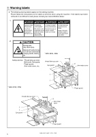
c Warning labels # The following warning labels appear on the sewing machine. Please follow the instructions on the labels at all times when using the machine. If the labels have been removed or are difficult to read, please contact your nearest - Brother International BAS-375E | Instruction Manual - English - Page 6
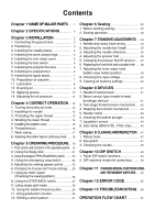
2. DIP switches inside the control box .......... 50 Chapter 11 CHANGING SPECIAL FUNCTIONS USING AND THE MEMORY SWITCHES ..... 52 Chapter 12 ERROR CODE 57 Chapter 13 TROUBLESHOOTING ... 59 OPERATION FLOW CHART 61 - Brother International BAS-375E | Instruction Manual - English - Page 7
Chapter 1 NAME OF MAJOR PARTS Chapter 1 NAME OF MAJOR PARTS Hand Pully Spool stand Emergency stop switch Reset switch Work clamp Power switch Floppy disk drive Programmer Operation panel Arm motor cover Dip sw Bobbin winder Beam sensor-type needle thread breakage detector Work clamp lift switch - Brother International BAS-375E | Instruction Manual - English - Page 8
Chapter 2 SPECIFICATIONS Chapter 2 SPECIFICATIONS Stitch type Sewing machine Rotary hook Needle Stitch length Max. sewing intermittent feed mode speed continuous feed mode Max. pattern size (X - Y) Max. number of stitches Work clamp lift stroke Intermittent lift stroke Test function - Brother International BAS-375E | Instruction Manual - English - Page 9
Chapter 3 INSTALLATION Chapter 3 INSTALLATION CAUTION Machine installation should only be carried out by a qualified technician. Contact your Brother dealer or a qualified electrician for any electrical work that may need to be done. The sewing machine head weighs more than 65 kg. The - Brother International BAS-375E | Instruction Manual - English - Page 10
r with the bolts u. 4. Place the screw holes in the left needle plate i, center needle plate o and right needle plate !0 on top of the needle plate support hases w so that the screw holes are aligned, and then secure them by tightening the screws. * For the BAS-364E, install the center needle plate - Brother International BAS-375E | Instruction Manual - English - Page 11
Make sure that the set screw i goes into the screw stop u of Y pulley shaft (A) t. 5. Installing the arm motor cover w e r t w q r 1. Move the feed mechanism q manually until it is as far into the machine as it will go. (The ball spline w should be extended fully toward the front when looking - Brother International BAS-375E | Instruction Manual - English - Page 12
of q the front cover at the bottom of the machine. e w 7. Installing the programmer box w i u y r 1. Attach the programmer box q to the needle plate support w using the screws. 2. Be sure to attach the two connectors r and t to the respective receptacles on the rear of the floppy disk - Brother International BAS-375E | Instruction Manual - English - Page 13
Chapter 3 INSTALLATION 9. Installing the spool stand Install the spool stand to the support of the panel. 10. Preparation of cassette When not using the presser plate lower q, put the teflon w tape on the rear of the cassette w. Note - Brother International BAS-375E | Instruction Manual - English - Page 14
11. Lubrication Chapter 3 INSTALLATION CAUTION Turn off the power switch before starting any cleaning work, otherwise the machine may operated if the foot switch is depressed by mistake, which could result in injury. Be sure to wear protective goggles and gloves when handling the lubricating oil - Brother International BAS-375E | Instruction Manual - English - Page 15
Chapter 3 INSTALLATION 12. Draining oil Remove and empty the waste oil tank q whenever it is full. The waste oil tank q is underneath the front right leg. q BAS-364E, 366E, 370E, 375E 9 - Brother International BAS-375E | Instruction Manual - English - Page 16
Chapter 3 INSTALLATION 13. Applying grease If the grease has run out, apply more grease in the places indicated by the arrows below. Note If you continue to operate the machine without any grease, it will cause abnormal noise and malfunctions to occur. BAS-364E, 366E, 370E, 375E 10 - Brother International BAS-375E | Instruction Manual - English - Page 17
Chapter 3 INSTALLATION 14. Adjusting the air pressure w r 1. Air pressure should be 0.5 MPa. The air pressure can be adjusted by pulling up and turning the control knob w on the integrator q. After adjustment is complete, push the control knob w downward to lock it. 2. If water stands in the - Brother International BAS-375E | Instruction Manual - English - Page 18
front, and then retighten set screw q. Note G Always make sure that the needle w is fully inserted facing the front. G If the needle is installed incorrectly, problems such q as needle breakage may occur. w BAS-364E, 366E, 370E, 375E 12 - Brother International BAS-375E | Instruction Manual - English - Page 19
Chapter 4 CORRECT OPERATION 3. Threading the upper thread CAUTION If the power switch needs to be left on when carrying out threading, be extremely careful to observe all safety precautions. The machine may operate if the foot switch is depressed by mistake, which could result in injury. (ex. - Brother International BAS-375E | Instruction Manual - English - Page 20
onto the spindle. 2. Thread the thread as shown in the illustration (in the case of the BAS-364E and 366E, there is no lower thread guide u), wind the thread around the bobbin several time in the direction shown by the arrow, and then press the bobbin presser q. 3. Turn the power switch - Brother International BAS-375E | Instruction Manual - English - Page 21
Chapter 4 CORRECT OPERATION w A q B Note If the bobbin thread is wound unevenly onto the bobbin, loosen nut q, and turn thread tension stud w to adjust so that the thread is wound evenly. If the bobbin is wound as in Fig. A, turn the stud clockwise, if Fig. B, turn the stud counterclockwise. 5. - Brother International BAS-375E | Instruction Manual - English - Page 22
6. Thread tension Chapter 4 CORRECT OPERATION Correct seam w Weaker Stronger Shorter Needle thread tension is too low Needle thread tension is too high Longer q Weaker Stronger e 1. Turn the adjustment screw q to adjust so that the length of the thread remaining at the needle point when the - Brother International BAS-375E | Instruction Manual - English - Page 23
Chapter 4 CORRECT OPERATION 7. Work clamp CAUTION If the power switch and air need to be left on when carrying out some adjustment, be extremely careful to observe all safety precautions. Do not touch any of the moving parts or press any objects against the machine when making adjustments, as this - Brother International BAS-375E | Instruction Manual - English - Page 24
change the setting of DIP switch as described in step 1.. Note If you operate a machine with one of the above model numbers at continuous feed, problems such machine seizure will occur. BAS-364E, 366E, 370E, 375E 18 - Brother International BAS-375E | Instruction Manual - English - Page 25
Chapter 5 OPERATING PROCEDURE Chapter 5 OPERATING PROCEDURE 1. Part names and functions of the operation panel y q POWER indicator When the power is turned on, the indicator lights to show that the power is on. w PROGRAM No. display Displays the program number 00 - 99. e Program select switch - Brother International BAS-375E | Instruction Manual - English - Page 26
Chapter 5 OPERATING PROCEDURE !0 Bobbin Thread COUNTER .......... Illuminates when bobbin thread counter mode has been selected using the indicator menu switch y. !1 SPLIT NO. indicator Illuminates when split No. mode has been selected using the menu switch y. !2 Dial The setting shown on the - Brother International BAS-375E | Instruction Manual - English - Page 27
Chapter 5 OPERATING PROCEDURE 2. Using the floppy disk A single pattern containing up to 20,000 stitches, and a maximum of 100 patterns (360,000 stitches) can be stored on a single 2HD floppy disk. w r q e Unlocked, writing possible Window open r Locked, writing impossible 1. Turn the power - Brother International BAS-375E | Instruction Manual - English - Page 28
, use a disk which has been pre-formatted as a 1.44 MB disk. (The programmer can be used to format these disks. Refer to the programmer instruction manual for details.) q TFD embroidery data can be embroidered after it has been converted by the programmer to BAS-370E data. q Restriction on using 2DD - Brother International BAS-375E | Instruction Manual - English - Page 29
Chapter 5 OPERATING PROCEDURE 3. Using the program R/W (Read/Write) switch Programmed stitch patterns stored on floppy disk can be read into memory, and newly programmed pat terns can be written to disk for permanent storage and later recall. Insert the floppy disk q containing or which is to - Brother International BAS-375E | Instruction Manual - English - Page 30
the emergency stop function is automatically activated, all operations stop, and the alarm sounds. If the alarm is sounding intermittently, correct the problem and press the reset switch w to cancel the emergency stop mode. If emergency stop function is not canceled even when EMERGENCY STOP switch - Brother International BAS-375E | Instruction Manual - English - Page 31
Chapter 5 OPERATING PROCEDURE 5. Adjusting the sewing speed control The sewing speed can be changed in steps of 100 rpm to the appropriate speeds for each stitch length setting. 1. Press the MENU switch y until the SPEED indicator o illuminates. 2. While pressing the STEP BACK switch !,7 turn the - Brother International BAS-375E | Instruction Manual - English - Page 32
Chapter 5 OPERATING PROCEDURE 7. Using the TEST switch (Checking the sewing pattern) CAUTION Do not touch any of the moving parts or press any objects against the machine while sewing, as this may result in personal injury or damage to the machine. Use the TEST switch to move the presser foot - Brother International BAS-375E | Instruction Manual - English - Page 33
Chapter 5 OPERATING PROCEDURE 8. Using the STEP BACK switch CAUTION Do not touch any of the moving parts or press any objects against the machine while sewing, as this may result in personal injury or damage to the machine. This switch is used to move the machine one stitch at a time in the - Brother International BAS-375E | Instruction Manual - English - Page 34
: "1" / "2" / "3" / "1" / "2"... q w e 4. When the start switch is pressed, only the pattern displayed on the display screen t will be sewn. Note As to split sewing, refer to the instruction manual of the programmer. BAS-364E, 366E, 370E, 375E 28 - Brother International BAS-375E | Instruction Manual - English - Page 35
Chapter 5 OPERATING PROCEDURE 10. Using the bobbin thread counter Set the bobbin thread counter to display number of pieces of the selected pattern which can be sewn with the amount of thread on the bobbin to avoid running out of bobbin thread in the middle of a pattern. t series !3 !4 !0 y !2 !7 - Brother International BAS-375E | Instruction Manual - English - Page 36
Chapter 5 OPERATING PROCEDURE 11. Using production counter Both PRO. NO. and B.T. COUNTER displays are available for the five-digit PRODUCTION counter. t series !3 w !4 !0 !1 !6 y !2 !5 !7 1. While Pressing the TEST switch !,5 press the B.T.SET switch !3 The B.T.COOUNTER indicator !0 and - Brother International BAS-375E | Instruction Manual - English - Page 37
Chapter 5 OPERATING PROCEDURE 12. Shifting a stitch pattern q Programs which have already been programmed can be moved up, down and to the left and right. (However, such patterns will be reset if the power supply is turned off or the program number is changed.) q The feed position can be set to the - Brother International BAS-375E | Instruction Manual - English - Page 38
Chapter 6 SEWING Chapter 6 SEWING CAUTION Turn off the power switch at the following times, otherwise the machine may operate if the foot switch is depressed by mistake, which could result in injury. G Threading G When replacing the bobbin and needle G When not using the machine and when leaving - Brother International BAS-375E | Instruction Manual - English - Page 39
Chapter 6 SEWING 2. Sewing operation ON OFF q w t e u y r 1. Turn the power switch q on. The POWER indicator on the operation panel will light. 2. Insert the floppy disk w. 3. Press the PROGRAM No. select switch e to select the desired program number. 4. Press Program Read/Write switch r. The - Brother International BAS-375E | Instruction Manual - English - Page 40
that they operate correctly before using the machine. Note See page 10 "Chapter 4 1.Turning the pulley by hand", and turn the pulley manually for all adjustments. 1. Needle and rotary hook timing q w 2.2 ± 0.3mm e Needle center 1. Turn the hand pulley so that the needle bar is 2.2 ± 0.3 mm - Brother International BAS-375E | Instruction Manual - English - Page 41
Chapter 7 STANDARD ADJUSTMENTS 2. Adjusting the needle bar height q w 0.5 - 2mm Needle center e 1. Turn the hand pulley so that rotary hook point q is aligned with the needle center. Remove cap w, loosen screw e, and raise or lower the needle bar so that the gap between the top of the needle - Brother International BAS-375E | Instruction Manual - English - Page 42
Chapter 7 STANDARD ADJUSTMENTS 4. Adjusting the presser foot Note If the presser foot is lowered too far, the work piece will shift when sewing. Also, if the presser foot is high, skipped stitches may occur. e r q w 1. Loosen screw q, set the bottom of the presser foot w lightly against the work - Brother International BAS-375E | Instruction Manual - English - Page 43
position of intermittent feed arm (L) t so that the screw i of the presser bar clamp u is positioned at the center of the slot on the intermittent support assembly o. Then tighten the screw y. If it is not necessary to move the presser foot up and down 1. Remove the stud screw !,0 and reattach link - Brother International BAS-375E | Instruction Manual - English - Page 44
Chapter 7 STANDARD ADJUSTMENTS 6. Replacing the fixed knife and movable knife Replacing the fixed knife 1. Turn the hand pulley by hand to raise the needle to the highest position. q w e r 2. Remove the two screws q and remove the needle plate w. 3. Remove the screw e, replace the fixed knife r - Brother International BAS-375E | Instruction Manual - English - Page 45
Chapter 7 STANDARD ADJUSTMENTS 7. Adjusting the inner rotary hook bobbin case holder position w w e r Loosen the bolt q. Adjust the position of the rotary hook bobbin case holder w so that there is no clearance between the bottom e of the rotary hook bobbin case holder w and the machine bed r, - Brother International BAS-375E | Instruction Manual - English - Page 46
Chapter 7 STANDARD ADJUSTMENTS 8. Checking the input voltage 1. Turn on the power switch. 2. Press the menu switch q until the X-SCALE indicator w illuminates. q¡ w 3. While pressing the TEST switch e, press the R/W switch r. e r 4. If the input voltage is normal, the input voltage conditions - Brother International BAS-375E | Instruction Manual - English - Page 47
Chapter 8 DEVICES Chapter 8 DEVICES Some of the specifications include optional devices as standard equipment. 1. Needle thread presser G The needle thread presser is used to enable the needle thread to be securely sewn underneath the material. G The needle thread presser presses the needle - Brother International BAS-375E | Instruction Manual - English - Page 48
Chapter 8 DEVICES 3. Two-stage thread tension mechanism (Option) G This mechanism is used to enable selection of the thread tension in two steps when sewing a single pattern. G It is useful when a different sewing tension is necessary while sewing a single pattern due to the sewing direction or - Brother International BAS-375E | Instruction Manual - English - Page 49
Temporarily install bottom plunger e with screws r. 3. Turn the pulley to lower the needle to the bottom dead center. 4. Hold up the bottom plunger e manually and adjust its position at the center of the hole in the plunger. Then, tighten screws r. 5. Secure the provided needle plate t with screws - Brother International BAS-375E | Instruction Manual - English - Page 50
Chapter 8 DEVICES 7. Jig pattern sensor (Option) If the work clamp foot is not appropriate for use with the programmed sewing pattern, an error will be displayed and the machine will enter the emergency stop condition. Setting the start position G At the sewing start position, attach reflector - Brother International BAS-375E | Instruction Manual - English - Page 51
Chapter 8 DEVICES 8. Sub clamp (BAS-370E, 375E only) This is used when the standard clamp alone cannot hold the work piece properly. When using the sub clamp, set DIP switch E-2 on the main circuit board. D B' E C Main circuit board r First-stage Second-stage 12345678 12345678 A B q w e - Brother International BAS-375E | Instruction Manual - English - Page 52
u t e y 90 ˚ Chapter 8 DEVICES Adjusting the cloth clamp lever fixed angle CAUTION Turn off the power switch before starting any cleaning work, otherwise the machine may operate if the foot switch is depressed by mistake, which could result in injury. When the sub clamp e is lowered, the attaching - Brother International BAS-375E | Instruction Manual - English - Page 53
Chapter 9 CLEANING AND INSPECTION Chapter 9 CLEANING AND INSPECTION CAUTION Turn off the power switch before starting any cleaning work, otherwise the machine may operate if the foot switch is depressed by mistake, which could result in injury. Be sure to wear protective goggles and gloves when - Brother International BAS-375E | Instruction Manual - English - Page 54
3. Checking the needle Chapter 9 CLEANING AND INSPECTION Always check that the tip of the needle is not broken before starting sewing. BAS-364E, 366E, 370E, 375E 48 - Brother International BAS-375E | Instruction Manual - English - Page 55
Chapter 10 DIP SWITCH Chapter 10 DIP SWITCH Note When changing DIP switch, the power must be off. 1. Panel DIP switch functions I DIP switch A (on side of operation panel, at the top) SW No. A-1 A-2 A-3 A-4 A-5 A-6 A-7 A-8 When ON Presser foot rises when presser lift switch is pressed, and does - Brother International BAS-375E | Instruction Manual - English - Page 56
Chapter 10 DIP SWITCH 2. DIP switches inside the control box DANGER Wait at least 5 minutes after turning off the power switch and disconnecting the power cord from the wall outlet before opening the face plate of the control box. Touching areas where high voltages are present can result in severe - Brother International BAS-375E | Instruction Manual - English - Page 57
Chapter 10 DIP SWITCH I DIP C (Lower left side of main circuit board) SW No. C-1 C-2 C-3 C-4 C-5 C-6 C-7 C-8 When ON Low speed at the sewing start and sewing end is approx. 260 rpm Low speed at the sewing start and sewing end is approx. 200 rpm Not added low speed data at the acute angle part - Brother International BAS-375E | Instruction Manual - English - Page 58
Chapter 11 CHANGING SPECIAL FUNCTIONS AND USING THE MEMORY SWITCHES Chapter 11 CHANGING SPECIAL FUNCTIONS AND USING THE MEMORY SWITCHES The functions of the switches on the operation panel can be changed to carry out special functions. Note All of the memory switches are set to OFF or the condition - Brother International BAS-375E | Instruction Manual - English - Page 59
Chapter 11 CHANGING SPECIAL FUNCTIONS AND USING THE MEMORY SWITCHES I Memory switches [00] - [0F] SW. No. memo-00 memo-01 memo-02 memo-03 memo-04 memo-05 memo-06 memo-07 memo-08 memo-09 memo-0A memo-0b memo-0c memo-0d memo-0E memo-0F When "on" Feed plate moves in the order X ¡ Y when moving to - Brother International BAS-375E | Instruction Manual - English - Page 60
Chapter 11 CHANGING SPECIAL FUNCTIONS AND USING THE MEMORY SWITCHES I Memory switches [00] - [2F] SW No. memo-20 memo-21 memo-22 memo-23 memo-24 memo-25 memo-26 memo-27 memo-28 memo-29 memo-2A memo-2b memo-2c memo-2d memo-2E memo-2F When "on" 100/500 stitch jump feeding is possible during test - Brother International BAS-375E | Instruction Manual - English - Page 61
Chapter 11 CHANGING SPECIAL FUNCTIONS AND USING THE MEMORY SWITCHES I Memory switches [30] - [3F] (Set using numbers instead of [on] or [oFF]) SW. No. memo-30 memo-31 memo-32 memo-33 memo-34 memo-35 memo-36 memo-37 memo-38 memo-39 memo-3A memo-3b memo-3c memo-3d memo-3E memo-3F Setting range - Brother International BAS-375E | Instruction Manual - English - Page 62
Chapter 11 CHANGING SPECIAL FUNCTIONS AND USING THE MEMORY SWITCHES I Memory Switches [40] - [4F] (Set using numbers instead of [on] or [oFF]) SW. No. Setting range Units Default memo-40 1 - 10 ✕ 7.5˚ 5 memo-41 1 - 10 ✕ 7.5˚ 5 memo-42 memo-43 memo-44 memo-45 memo-46 memo-47 memo-48 memo- - Brother International BAS-375E | Instruction Manual - English - Page 63
voltages are present can result in severe injury. Note G If an operation problem occurs, buzzer will sound and an error code will appear on the display is activated or its connection is not correct. Z motor or Z servo amp trouble. Turn off the power and check. Turn off the power, and then turn - Brother International BAS-375E | Instruction Manual - English - Page 64
Chapter 12 ERROR CODE code Cause E. c3 X motor or X servo amp trouble. E. c4 Y motor or Y servo amp trouble. E. c6 E. c7 E. c8 E. c9 E. cA E. d0 +X over-travel error. -X over-travel error. +Y over-travel error. -Y over-travel error. Feed error Air pressure has dropped. E. E1 - Brother International BAS-375E | Instruction Manual - English - Page 65
Chapter 13 TROUBLESHOOTING Chapter 13 TROUBLESHOOTING List of adjustments Problem Check and remedy Presser foot does not rise. G Is the presser arm stiff? / Apply some grease to the sliding surface of the presser arm. G Is - Brother International BAS-375E | Instruction Manual - English - Page 66
Chapter 13 TROUBLESHOOTING Problem Needle breaks. Check and remedy G Is the needle touching the rotary hook? / Adjust while referring to "Needle and rotary hook timing" and "Adjusting the needle - Brother International BAS-375E | Instruction Manual - English - Page 67
Feed stop TEST indicator goes out When thread breaks or bobbin thread runs out Press emergency stop switch Machine stops, alarm sounds Remove problem Press emergency stop switch Thread trimmer operates, alarm stops Press STEP BACK switch Press STEP BACK switch Work clamp moves one stitch at - Brother International BAS-375E | Instruction Manual - English - Page 68
INSTRUCTION MANUAL BROTHER INDUSTRIES, LTD. 15-1, Naeshiro-cho, Mizuho-ku, Nagoya 467-8561, Japan. Phone: 81-52-824-2177 Printed in Japan 151-V64,V66,V70,V75 S93V64-002 2001.04. H (1)
-
 1
1 -
 2
2 -
 3
3 -
 4
4 -
 5
5 -
 6
6 -
 7
7 -
8
-
9
-
10
-
11
-
12
-
13
-
14
-
15
-
16
-
17
-
18
-
19
-
20
-
21
-
22
-
23
-
24
-
25
-
26
-
27
-
28
-
29
-
30
-
31
-
32
-
33
-
34
-
35
-
36
-
37
-
38
-
39
-
40
-
41
-
42
-
43
-
44
-
45
-
46
-
47
-
48
-
49
-
50
-
51
-
52
-
53
-
54
-
55
-
56
-
57
-
58
-
59
-
60
-
61
-
62
-
63
-
64
-
65
-
66
-
67
-
68
 |
 |

INSTRUCTION MANUAL
Please read this manual before using the machine.
Please keep this manual within easy reach for quick reference.
PROGRAMMABLE ELECTRONIC PATTERN SEWER
BAS
-
364E,366E
BAS
-
370E,375E