Brother International BE-1201B-AC Tubular To Cap - English
Brother International BE-1201B-AC Manual
 |
View all Brother International BE-1201B-AC manuals
Add to My Manuals
Save this manual to your list of manuals |
Brother International BE-1201B-AC manual content summary:
- Brother International BE-1201B-AC | Tubular To Cap - English - Page 1
9) Slide the cap driver attachment through the sewing arm of the machine. 10) Slide the guide bar (F) into the hole to the rear of the arm until two screws when not using cap drive system, also please use the proper screws. Other screws can cause mechanical problems. 14) Tighten the phillips
-
 1
1
 |
 |
B
B
E
E
S
S
-
-
9
9
1
1
6
6
,
,
9
9
0
0
1
1
,
,
1
1
2
2
1
1
6
6
,
,
1
1
2
2
0
0
1
1
For Technical Assistance Please Call Toll Free
1-877-4BROTHER
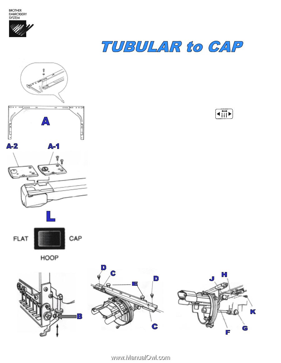
With the power to the machine in the ON position.
1) Remove the tubular arm (
A
) attachment by removing the two long screws with a Phillips and
flat head screw head as well as the lock washers and flat washers. Rethread the screws and
washers into an empty screw hole of the tubular frame to help avoid losing them.
2) Remove the flat needle plate (
A-1
) and replace with the cap needle plate (
A-2
).
3) Turn the machine off and move the switch (
L
) to “CAP” mode and turn the power back on.
4) Move the needle case to needle #1 using the needle select button
.
5) Turn the pulley in the direction of the arrow to 200 degrees.
6) Loosen the screw that secures the presser foot (
B
) and adjust the height of the presser foot to
the thickness of two business cards or one credit card and retighten screw.
7) Turn the pulley
backwards
to 100 degrees and raise presser foot with lever.
8) Install the metal bar with the “
L
” stamped on and attach over the locator pins (
C
) making sure
that the stamped “
L
” is on the left side facing up. Secure with the long black thumbscrews (
D
).
9) Slide the cap driver attachment through the sewing arm of the machine.
10) Slide the guide bar (
F
) into the hole to the rear of the arm until it stops
11) Tighten the black thumb knob (
G
) to secure the guide bar.
12) Slide the cap driver attachment towards the rear of the machine and position over the
metal bar, with L stamped on it, and secure with the two shorter black thumbscrews (
E
).
12) Swing the “L” shaped plate (
H
) up behind the pantograph.
13) Attach the two screws (
K
).
NOTE:
Do not
attach these two screws when not using cap drive
system, also please use the proper screws. Other screws can cause mechanical problems.
14) Tighten the phillips or thumbscrew (
J
) located on the right side of the cap system.
Note:
When securing this screw please be sure it has both a spring washer and flat washer.
This
Remove this screw on
each side
Revised 1/10/05