Brother International DB2-B737 Network Users Manual - English
Brother International DB2-B737 Manual
 |
View all Brother International DB2-B737 manuals
Add to My Manuals
Save this manual to your list of manuals |
Brother International DB2-B737 manual content summary:
- Brother International DB2-B737 | Network Users Manual - English - Page 1
DC MOTOR SERVICE MANUAL MD-802 (Single-Phase Type) MD-812 (Three-Phase Type) ...Z. Iva I (~ bay .8* trot s rst: tr otI BROTHER INDUSTRIES, LTD. mAt-±rwit lwnwwi - Brother International DB2-B737 | Network Users Manual - English - Page 2
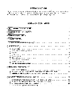
code 11 Standing work machine 12 pi Application to production control system 13 ((OPERATION INSTRUCTION 14 Installation of operation box 14 M Motor and control box (Models DB2-B737 • B747 • B748 • B791 • B793 • B795 • B798) 14 0 Operation box (Models DB2-B737 • B747 • B748 • B791 • B793 - Brother International DB2-B737 | Network Users Manual - English - Page 3
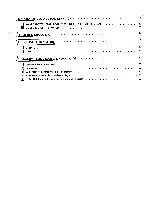
OF CONNECTOR PANEL)) 22 M Model DB2-B737 • B747 • B748 • B791 • B793 • B795 • B798 (Type 300B) 22 Model DB2-B738 (Type #4708) 23 TROUBLESHOOTING 24 CHECKINGTHE MOTOR© 25 111 Motor 25 ri Brake 25 CHECKINGTHE MACHINESOLENOID)S) 26 111 Solenoid load of the machine 26 121 Hem sensor - Brother International DB2-B737 | Network Users Manual - English - Page 4
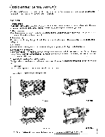
OF THE MOTOR *The Brother DC motor is best suited for the energy saving works. To save sewing labor and enhance the for the following sewing machines. [DB2-B7371 4 ,7 [DB2-6738] 4 [DB2-67911 *The DC motor is also applied to the automatic thread trimming machines, models DB2-6748, 8795, - Brother International DB2-B737 | Network Users Manual - English - Page 5
Ai 8 0 IA B I 0 0 Isom] ED ED Operation Box E-2 brother E-4 -4 • il El 0 All \ ,I c T , A 8 C O I I III: . 0 m. rSc I A! t0 RIO@EIMORI El m './ X V V se ES D C ID N ea I Operation Box E-4 Machine Head to be Applied [DB2-B737 • B747 • B748 • B791 • B793 • B795 • B798] Power - Brother International DB2-B737 | Network Users Manual - English - Page 6
enclosed by the broken line indicate where high voltage is applied. Handle these sections with great care. CAUTION: 1. In setting down the machine head or touching the needle, be sure to turn off the power switch and confirm the pilot lamp "OFF". 2. Ground codes are provided for both single-phase - Brother International DB2-B737 | Network Users Manual - English - Page 7
motor O. Then the signal from the synchronizer 0, mounted on the pulley of the sewing machine, is sent to the control box Q and the brakes are applied so that the operation of the sewing machine is stopped at the needle down stop position set by the synchronizer 0. 3. When the treadle is stepped on - Brother International DB2-B737 | Network Users Manual - English - Page 8
Drawing for Mounting the Motor wiC 160 80 56 20 025 R10 015 ± 0.1 3-08.5 Ln R10 042 0 LO O O Ce) 60 • N 0 cN o N R10 0co - Brother International DB2-B737 | Network Users Manual - English - Page 9
. Check the belt tension. *The machine rotates counterclockwise as seen from the pulley side. *Adjust the belt 0 by loosening the set screw 0 and turning the nut 0 so that it loosens about 10 mm when pressed by finger. 2 Needle position detector (synchronizer) Model DB2-B747 • B791 • B793 • B795 - Brother International DB2-B737 | Network Users Manual - English - Page 10
Model DB2-B737 • B748 Higher Lower Lower Higher 0 Needle up stop Thin, regular materials: 10 ^ 12 mm Thick materials: 10 --14 mm Reference line 0 Needle down stop 18 -- 22 mm *The synchronizer detects the needle position with two sensors. The thread trimmer signal is timed to the needle - Brother International DB2-B737 | Network Users Manual - English - Page 11
Model DB2-B737) The high speed volume, backtack stitch volume, power lamp, needle position switch, one-stitich modification switch, slow start switch and connector for synchronizer and connector for control box are arranged on the front of the control box. All these parts maximum sewing speed volume - Brother International DB2-B737 | Network Users Manual - English - Page 12
4 Treadle C2i OJ Fig. A Fig. B 151 Brush replacement 0 a O O ..; 0 Stepping Pressure *If the machine starts running at low speed just by placing your foot on the treadle or by stepping on it lightly, the adjustment is required to change - Brother International DB2-B737 | Network Users Manual - English - Page 13
6 Motor brake spacing 0 m m m mo m m mm mm mmom 0.2 mm 0.1 mm O 0.15 mm Window fro adjusting the brake spacing 0.3 mm *Adjust the brake spacing when about two years have passed. And also adjust when the brake generates abnormal noises and does not stop stably. Adjustment Procedures 1. It is - Brother International DB2-B737 | Network Users Manual - English - Page 14
and the treadle lever are fixed for the standing work machine. In modifying to the standing work machine, do not fail to turn off the power switch before connecting/disconnecting the plug. 1. Code Connection Model 8737 Model 8738 0401011-00,4100setsRe%. Go. Plug A Plug B Ce$Ce 0 O 0 O O OO - Brother International DB2-B737 | Network Users Manual - English - Page 15
9 Application to production control system 1. Models DB2-B737 • B747 • B791 • B793. B795- B798 * Control circuit board 1 Emitter 2 Terminal not used 2. Model B738 Collector 1 *With special connectors (cycle output), connect the machine to the external equipments. *Output signals are sent from - Brother International DB2-B737 | Network Users Manual - English - Page 16
OPERATION INSTRUCTION 1 Installation of operation box Models DB2-B737 • B747 • B748 • B791 • • :g• Models DB2-B793 • B795- B798 0 0 Installing on the Machine Head 1. Remove the two screws 0 from the back of the arm bed. 2. Four screws 0 are provided. Use two large screws for the model B737. And - Brother International DB2-B737 | Network Users Manual - English - Page 17
3 Operation box (Models DB2-B737 • B747 • B791 • B793 • B795 • B798) *The switch settings and the number of stitches cannot be changed during the machine operation. Check the preset switch settings and the preset number of stitches before working with the machine. *When the backtack switch is - Brother International DB2-B737 | Network Users Manual - English - Page 18
and the correction switch is ON. If the actuator is pressed while the machine is operating, the machine enters the reverse sewing mode. When the machine is at the sewing start position after thread trimming, the machine does not move even if the actuator is pressed. • . . Thread trimming (Thread - Brother International DB2-B737 | Network Users Manual - English - Page 19
Thread trimming activated after end backtack by reversing the treadle. No.7 Fixed stitch sewing and end backtack No.8 Start/end backtack and fixed stitch sewing Fixed stitch NI 1 A i B/ NI Fixed stitch I /B/ Ii"A Thread trimming activated by reversing the treadle. No.9 Fixed stitch and thread - Brother International DB2-B737 | Network Users Manual - English - Page 20
03 z .5 a) C C ra h FBI C GACNVDo- 7- Treadle unit Reg White allow Black O ang +15V Blue Gray Pu plc Oman ~ O 06o\l'oli 5 w soV Machine head Reverse switch Reverse solenoid 7431 Thread wiper solenoid 5.052 Thread trimming solenoid 6.712 7 4 O 00 3 Solenoid presser foot lifter I5W - Brother International DB2-B737 | Network Users Manual - English - Page 21
• 13) "IZ2 • co .a5.) • O co, N co 717, .) .5 o zO., O w gO -C3 3 E O > ng < 2 'PI) co) vi 2 -o _c o g O_ d o g 0 8 .4 .U04i E-0 . c..) Machine head Reverse solenoid 7.4O Reverse switch Thread wiper solenoid 5.052 Thread trimming solenoid 6.742 4 0 00 3 Solenoid presser - Brother International DB2-B737 | Network Users Manual - English - Page 22
7154 14-4 O co ti 7c) O co O •- 0a). • 5 O 0 5•- +.4 O O o .0 Ce3 0COI N g "" _c Q O a) a) O 7cr) O C O a) c/2 O O E▪-• g CY) Potentiometer 3 Hem detection Machine head Solenoid presser foot Reverse switch lifter Reverse solenoid 7.4O 2 7( 0 4 Cycle o tput Thread wiper 5.0O - Brother International DB2-B737 | Network Users Manual - English - Page 23
CO CCI 0 4) 2 5; • N co cOo_ 7,5, 2 0 o < 4 O co) -arO.)) Vco) to) "" O _c O cb a) O a) • O 11) rO N Potentiometer 3 2 Hem detection Machine head Thread wiper solenoid 5.00 Reverse Reverse solenoid 7.40 Cycle utput 2 2 4 8 4 0 Thread trimming solenoid 6.7O 2 3 Solenoid - Brother International DB2-B737 | Network Users Manual - English - Page 24
CONNECTOR PANEL 1 Model DB2-B737 • B747 • B748 • B791 • B793 • B795 • B798 (Type 3O0B) For standing work O th` 0 CD CD Machine head Presser foot No. Synchronizer 1 GND 2 DC + 5 V 3 Needle down 4 0 V 5 NO. SYC 6 GND 7 Needle up 8 Encoder 9 10 Operation box GND Din Cin Bin Ain Cout - Brother International DB2-B737 | Network Users Manual - English - Page 25
2 Model DB2-B738 (Type #47OB) Potentiometer Cycle output 2 Needle position switch Hem detection O Correction C)SC) 00C) switch ArT\ \Li 0 0 0 For standing work Machine head Brake scp() Presser foot lifter Cycle output No. 2P connector 1 Collector 2 Emitter 3 4 5 6 Hem - Brother International DB2-B737 | Network Users Manual - English - Page 26
of the detailed parts (semiconductors) for maintenance. Trouble Check Point Parts to Be Replaced Ref. Page 1. The machine does not run machine pulley is so heavy to turn manually. [The machine or the motor (brake lining) is locked. Remove the trouble cause and turn on the power. Then the machine - Brother International DB2-B737 | Network Users Manual - English - Page 27
at any position between 1 (yellow) and 2 (yellow) with the resistance range xl, it is normal. 1. Remove the brake code (2P connector) from the connector part of the control box. 2. Measure with the tester set in the resistance range as follows. •If the tester reads approx. 7-9 ohm when measured at - Brother International DB2-B737 | Network Users Manual - English - Page 28
5 10 7 GND Thread wiper solenoid Thread trimming solenoid Presser foot lift connecter Solenoid GND 4 6 1 Knee switch 1. Remove the load connector (12P connector) of the machine from the connector part of the control box. 2. Measure with the tester set in the resistance range xl as follows - Brother International DB2-B737 | Network Users Manual - English - Page 29
HD 74LS 259 Drive Tr ic 6 HDLS -- I/ 259 ID- Drive Tr Machine brake Trimmer solenoid Wiper solenoid Reverse feed solenoid Low speed Back tack speed High speed 7 ). S LED PC1 PC2 Operation panel Set Ply sensor Input Sewing mode Programme Start tack End tack Repeat Auto SP Slow start Half step - Brother International DB2-B737 | Network Users Manual - English - Page 30
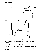
4 B737 Machine Control System Block Diagram MD-812-300B Pedal Front SW Rear SW Actuator SW Presser SW Synchronizer DN, UP ENC Hic 1 INP circuit Transformer +35V Power supply +12V +5V 01V Hic 3 ENC cont Motor lock protective Power ON-OFF detection ) CPU MB8841 ) Hic 2 Drive circuit Machine - Brother International DB2-B737 | Network Users Manual - English - Page 31
151 B737. B738 Motor Drive Control System Block Diagram Source IC.34, O Fuse Fuse MD-812-300B MD-812-470BR BD SCR Earth PTR C E C Base Emitter TH M -a - Brother International DB2-B737 | Network Users Manual - English - Page 32
BROTHER INDUSTRIES, LTD. HEAD OFFICE: No. 35, 9-CHOME, HORITA-DORI, MIZUHO-KU, NAGOYA, JAPAN 467 CABLE: BROTHER NAGOYA,
-
 1
1 -
 2
2 -
 3
3 -
 4
4 -
 5
5 -
 6
6 -
 7
7 -
8
-
9
-
10
-
11
-
12
-
13
-
14
-
15
-
16
-
17
-
18
-
19
-
20
-
21
-
22
-
23
-
24
-
25
-
26
-
27
-
28
-
29
-
30
-
31
-
32
 |
 |

DC
MOTOR
SERVICE
MANUAL
MD
-802
(Single
-Phase
Type)
MD
-812
(Three
-Phase
Type)
trot
s
rst:
tr
ot
I
...Z.
Iva
(~
I
bay
.8*
BROTHER
INDUSTRIES,
LTD.
mAt-±rwit
lwnwwi