Brother International DCP 8080DN Service Manual
Brother International DCP 8080DN - B/W Laser - All-in-One Manual
 |
UPC - 012502622697
View all Brother International DCP 8080DN manuals
Add to My Manuals
Save this manual to your list of manuals |
Brother International DCP 8080DN manual content summary:
- Brother International DCP 8080DN | Service Manual - Page 1
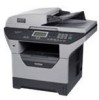
Laser FAX/MFC SERVICE MANUAL MODEL: DCP-8080DN/8085DN MFC-8480DN/8880DN/8890DW Read this manual thoroughly before maintenance work. Keep this manual in a convenient place for quick and easy reference at all times. January 2009 SM-FAX105 Confidential - Brother International DCP 8080DN | Service Manual - Page 2
United States and/or other countries. Microsoft, Windows, Windows Server and Internet Explorer are registered trademarks of Microsoft Corporation in the United States and/or other countries. Linux © Copyright Brother 2009 All DCP-8080DN DCP-8085DN MFC-8480DN MFC-8880DN MFC-8890DW Duplex Print/ Scan - Brother International DCP 8080DN | Service Manual - Page 3
for after-sales service of the Laser Multi-Function Center (hereinafter referred to as "the machine"). This information is vital to the service personnel to maintain the high printing quality and performance of the machine. This service manual covers the DCP-8080DN/8085DN, MFC-8480DN/8880DN/8890DW - Brother International DCP 8080DN | Service Manual - Page 4
(Technical Information). A thorough understanding of this printer, based on information in this service manual and service information bulletins, is required for maintaining its print quality performance and for improving the practical ability to find the cause of problems. ii Confidential - Brother International DCP 8080DN | Service Manual - Page 5
sure that you use one of the following interface laser diode which produces invisible laser radiation in the laser unit. You should not open the laser unit under any circumstances. Caution Use of controls or adjustments or performance of procedures other than those specified in this User's Guide - Brother International DCP 8080DN | Service Manual - Page 6
radiation Maximum radiation power: Wave length: Laser class: 5 mW 770 - 810 nm Class 3B ■ EU Directive 2002/96/EC and EN50419 (European Union only) This equipment is marked with the above recycling - Brother International DCP 8080DN | Service Manual - Page 7
Brother International Corporation 100 Somerset Corporate Boulevard P.O. Box 6911 Bridgewater, NJ 08807-0911 USA Telephone: (908) 704-1700 declares, that the products Product name: Laser Printer DCP-8080DN/8085DN, MFC Class B digital device, pursuant instructions, the interference by one or more of - Brother International DCP 8080DN | Service Manual - Page 8
Class B digital apparatus complies with Canadian ICES-003. Cet appareil numérique de la classe B est conforme à la norme NMB-003 du Canada. ■ Laser Safety (110 to 120 volt model only) This machine is certified as a Class 1 laser product under the U.S. Department of Health and Human Services (DHHS - Brother International DCP 8080DN | Service Manual - Page 9
CAUTION: When the machine during servicing is operated with the cover open, the regulations of VBG 93 and the performance instructions for VBG 93 are valid. CAUTION: In case of any trouble with the laser unit, replace the laser unit itself. To prevent direct exposure to the laser beam, do not try - Brother International DCP 8080DN | Service Manual - Page 10
cautions that must be observed to service the printer properly or prevent damage to the printer. Note : • Indicates notes and useful tips to remember when servicing the printer. ** Listed below are the various kinds of "WARNING" messages included in this manual WARNING Always turn off the power - Brother International DCP 8080DN | Service Manual - Page 11
WARNING If you analyze malfunctions with the power plug inserted into the power outlet, special caution should be exercised even if the power switch is OFF because it is a single pole switch. WARNING DO NOT use flammable substances, any type of spray or any organic solvent/liquids contains alcohol - Brother International DCP 8080DN | Service Manual - Page 12
CHAPTER 1 SPECIFICATIONS - Brother International DCP 8080DN | Service Manual - Page 13
. CONTENTS 1. COMPONENTS ...1-1 2. SPECIFICATIONS LIST 1-2 2.1 Printing ...1-2 2.2 Functions ...1-3 2.3 Electronics and Mechanics 1-5 2.4 Network Connectivity 1-6 2.5 Service Information 1-8 2.6 Paper ...1-9 2.6.1 Paper handling 1-9 2.6.2 Media specifications 1-10 2.6.3 Type and size of paper - Brother International DCP 8080DN | Service Manual - Page 14
of the following major components: ADF Unit Scanner Unit Panel Unit NCU PCB Joint Cover ASSY Outer Chute ASSY Back Cover Driver PCB Speaker ASSY Laser Unit Side Cover R Rear Chute ASSY Fuser Unit Access Cover Side Cover L Main PCB Fig. 1-1 Frame Unit Toner LED PCB ASSY Process Cover - Brother International DCP 8080DN | Service Manual - Page 15
MFC MFC MFC 8080DN 8085DN 8480DN 8880DN 8890DW Print method Electrophotography by semiconductor laser beam scanning Laser Method: 1 polygon motor, 1 laser beam Wavelength: 770 nm - 810 nm Output: 5 mW (Max) Laser class: Class3 B Resolution 1200 dpi *1, HQ1200 (2400x600dpi) Windows® 2000/XP - Brother International DCP 8080DN | Service Manual - Page 16
fonts, 13 bar codes BR-Script 3 66 scalable fonts (PostScript® 3™) Model Printer driver Windows® DCP DCP MFC MFC MFC 8080DN 8085DN 8480DN 8880DN 8890DW PCL driver for Windows 2000 Professional, XP Home Edition, XP Professional Edition, XP professional x64 Edition, Server - Brother International DCP 8080DN | Service Manual - Page 17
Version Processor Speed Windows® Apple® Macintosh® Windows Vista® Intel® Pentium® 4 or equivalent 64-bit supported CPU Windows Server® 2003 x64 Edition Windows® XP Professional x64 Edition Windows Server® 2003 Windows® XP Home Edition Windows® XP Professional Windows® 2000 Professional OS - Brother International DCP 8080DN | Service Manual - Page 18
2.3 Electronics and Mechanics Model DCP DCP MFC MFC MFC 8080DN 8085DN 8480DN 8880DN 8890DW Power consumption Printing 531 × 451 × 475 mm (20.9 × 17.8 × 18.7 in.) Weight Without Carton with drum unit and toner cartridge Approx. 18.1 kg (39.9 lb) Approx. 18.4 kg (40.6 lb) Approx. 18.3 kg - Brother International DCP 8080DN | Service Manual - Page 19
Web Services Windows® XP and Windows® 2000 TCP/IP printing Mac OS® X 10.3.9 or greater printing *1 If you want to use the IPv6 protocol, visit http://solutions.brother.com for more information. Management utility BRAdmin Professional 3 *2 for Windows (Brother original Windows utility for printer - Brother International DCP 8080DN | Service Manual - Page 20
responder, Web Services Print, CIFS Client, SNTP Network type IEEE 802.11b/g wireless Frequency 2412 - 2472 MHz RF channel US/Canada 1 - 11 is supported only between the Brother printer and an access point for PC's running Windows Server® 2003 x64 Edition and Windows® XP Professional x64 - Brother International DCP 8080DN | Service Manual - Page 21
replacement parts: Parts Approximate Life (pages) Fuser unit 100,000 Laser unit 100,000 PF kit China MP: 25,000 Tray 1/2: 100,000 India MP: 12,000 Tray 1/2: 80,000 Others MP: 50,000 Tray 1/2: 100,000 * As for periodical replacement parts, refer to CHAPTER 4 in the Service Manual - Brother International DCP 8080DN | Service Manual - Page 22
2.6 Paper 2.6.1 Paper handling Model DCP 8080DN DCP 8085DN MFC 8480DN MFC 8880DN MFC 8890DW Paper Standard 250 sheets Input *1 tray Multipurpose tray 50 Sheets (Plain)/ 3 Sheets (Envelope) Option 250 sheets ADF up to 50 sheets (Xerox4024 20lbs, environment: - Brother International DCP 8080DN | Service Manual - Page 23
Standard/ Option) Multi-purpose tray Duplex DCP DCP MFC MFC MFC 8080DN 8085DN 8480DN 8880DN 8890DW Plain paper, Bond Canada. 2.6.3 Type and size of paper The printer loads paper from the installed paper tray or the multi-purpose tray. The name s for the paper trays in the printer driver - Brother International DCP 8080DN | Service Manual - Page 24
MP Tray Choose the DX media type from the printer driver Plain paper Plain paper 75 to 105 g/m2 Yes neutral paper. Do not use acidic or alkaline paper. • Use long-grain paper. • This printer can use recycled paper that meets DIN 19309 specifications. • DO NOT use ink jet paper because it - Brother International DCP 8080DN | Service Manual - Page 25
logical page length Distance from edge of physical page to edge of logical page A Note : • "Logical page" shows the printable area for a PCL driver. • "Printable area" shows mechanical printable area of the machine. • Therefore, the machine can only print within the shaded area when you use a PCL - Brother International DCP 8080DN | Service Manual - Page 26
The table below shows the printable areas when printing on Portrait for each paper size. Size Letter Legal Folio Executive A 4 A 5 A 6 B 5 (JIS) B 5 (ISO) B 6 (ISO) Envelope Monarch Envelope Com-10 Envelope DL Envelope C5 HAGAKI A4 Long A 215.9mm 8.5" (2,550dots) 215.9mm 8.5" (2,550dots) 215.9mm - Brother International DCP 8080DN | Service Manual - Page 27
Size DL Long Edge 3X5 A 220.0mm 8.66" (2,598dots) 76.2mm 3.00" (900dots) B 110.0mm 4.33" (1,299dots) 127.0mm 5.00" (1,500dots) C 207.0mm 8.17" (2,450dots) 63.5mm 2.50" (750dots) D 110.0mm 4.33" (1,299dots) 127.0mm 5.00" (1,500dots) E 6.26mm 0.25" (74dots) 6.35mm 0.25" (75dots) F G 4.2mm 0mm - Brother International DCP 8080DN | Service Manual - Page 28
logical page length Distance from edge of physical page to edge of logical page A Note : • "Logical page" shows the printable area for a PCL driver. • "Printable area" shows mechanical printable area of the machine. • Therefore, the machine can only print within the shaded area when you use a PCL - Brother International DCP 8080DN | Service Manual - Page 29
The table below shows the printable areas when printing on Landscape for each paper size. Size Letter Legal Folio Executive A 4 A 5 A 6 B 5 (JIS) B 5 (ISO) B 6 (ISO) Envelope Monarch Envelope Com-10 Envelope DL Envelope C5 HAGAKI A4 Long A B 279.4mm 215.9mm 11.0" 8.5" (3,300dots) (2,550dots) - Brother International DCP 8080DN | Service Manual - Page 30
Size DL Long Edge 3X5 A 110mm 4.33" (1,299dots) 127mm 5.00" (1,500dots) B 220mm 8.66" (2,598dots) 76.2mm 3.00" (900dots) C 102mm 4.00" (1,199dots) 116.8mm 4.60" (1,380dots) D 220mm 8.66" (2,598dots) 76.2mm 3.00" (900dots) E 4.0mm 0.16" (50dots) 5.0mm 0.20" (60dots) F G 4.2mm 0mm 0.16" ( - Brother International DCP 8080DN | Service Manual - Page 31
paper tray. • When a smaller size paper than A4 or Letter is printed, the temperature on both edges of the fuser unit is much higher than the temperature on the center of the unit where the paper is fed depending on the setting or model. Therefore, the print speed is slowed in order to - Brother International DCP 8080DN | Service Manual - Page 32
Telephone Model DCP 8080DN DCP 8085DN Handset No Chain Dialing No Automatic Redial No PBX Feature No Speaker Phone No Hold/Mute Key No Music on Hold No Speaker Volume No Ring Volume No Beeper Volume Yes (3 steps + OFF) One-Touch Dial No Speed Dial No Figures of One-Touch - Brother International DCP 8080DN | Service Manual - Page 33
No Quick-Scan (Memory transmission) Memory Transmission (ITU-T Chart) ECM (Error Correction Mode) Error Re-Transmission No Broadcasting No Manual Broadcasting No Fax Forwarding No DCP 8085DN MFC 8480DN MFC 8880DN MFC 8890DW 33.600bps Approx. 2sec. (Brother#1 Std resolution - Brother International DCP 8080DN | Service Manual - Page 34
) Fax Rx Stamp No DCP 8085DN MFC 8480DN Yes MFC 8880DN MFC 8890DW Yes Yes Yes Yes Yes Yes up to 500 pages (ITU-T Test Chart, Standard Resolution, JBIG) up to 600 pages (Brother #1Chart, Standard Resolution, JBIG) Yes 2.11 List/Report Model DCP 8080DN Activity Report/Journal No Report - Brother International DCP 8080DN | Service Manual - Page 35
% in 1% increments Resolution (dpi) Maximum. 1200 x 600 dpi Auto Duplex Scanning No Yes No Yes Copy Manual Duplex Copy No N in 1 Yes Poster No Image Enhancement No 2.13 Scanner Model DCP 8080DN DCP 8085DN MFC 8480DN Color/Mono Color/Mono Resolution (Optical) (Glass) Maximum 600 - Brother International DCP 8080DN | Service Manual - Page 36
2.14 USB Host Model PictBridge Direct Print Media Drive DCP 8080DN No Yes No DCP 8085DN MFC 8480DN MFC 8880DN MFC 8890DW 1-23 Confidential - Brother International DCP 8080DN | Service Manual - Page 37
CHAPTER 2 THEORY OF OPERATION Confidential - Brother International DCP 8080DN | Service Manual - Page 38
from the MP tray 2-19 3.3.7 Paper feeding from the LT tray (Tray2 2-19 3.4 Toner Cartridge...2-20 3.4.1 Methods for Detecting Toner Life 2-20 3.4.2 Cartridge life 2-21 3.4.3 New toner detection 2-22 3.5 Print ...2-25 3.5.1 Basic Principle 2-25 3.5.2 Print Process 2-26 3.6 Sensors position - Brother International DCP 8080DN | Service Manual - Page 39
LAN only) Digital camera (PICT bridge) LAN (For the models with the LAN only) Control panel Centronics parallel interface USB interface WLAN PCB LAN interface USB interface Line Control Section Fax data Printer data NCU* Speaker ADF unit Scanner unit Laser printing unit Paper Low - Brother International DCP 8080DN | Service Manual - Page 40
relay PCB New toner sensor Wireless LAN (Wireless LAN model) Polygon motor Laser diode PCB NCU PCB Main PCB CCD module Home position sensor Scanner motor FB Scanner unit ASSY Speaker ASSY Fig. 2-2 Low-voltage power supply Rear relay PCB Paper eject sensor Fuser thermistor DX unit sensor PCB DX - Brother International DCP 8080DN | Service Manual - Page 41
3. MECHANICS 3.1 Cross-section Drawing - Printer part Paper stack lever Transfer roller Eject roller 2 Back cover Heat roller Eject roller 1 Paper eject actuator Pressure roller Duplex unit Paper tray Paper tray (LT unit) Laser unit Corona wire Exposure drum Develop roller Fig. 2-3 2-3 MP tray - Brother International DCP 8080DN | Service Manual - Page 42
-up roller Document front sensor actuator 1 Document front sensor actuator 2 Document front sensor 1 Paper feed roller 3 HP sensor CCD module Paper feed roller 4 Flap A Fig. 2-4 Guide Shaft CCD drive belt Pulley ASSY 2-4 Confidential - Brother International DCP 8080DN | Service Manual - Page 43
document feeder (ADF). The scanner unit consists of a scanner top cover, CCD unit and scanner base. Document cover ADF ADF & document cover ASSY Top cover White-level reference film CCD module Guide shaft Belt Pulley ASSY Scanner unit (Scanner cover) Scanner base Fig. 2-5 2-5 Confidential - Brother International DCP 8080DN | Service Manual - Page 44
data so that the image is generated on the CCD. 2. Driving of the CCD unit The CCD unit is supported by the CCD rail and assembled on the CCD drive belt. When the CCD motor is rotated clockwise, the CCD unit on the CCD drive belt scans the document while sliding to the right hand side. In this - Brother International DCP 8080DN | Service Manual - Page 45
operation is started. The CCD motor is rotated so that its action is transferred to the CCD drive belt through the gear train. The CCD unit scans the document while sliding to the right hand side. Guide shaft CCD unit ADF unit Drive plate ASSY (Scanner motor FB) Pulley ASSY FFC cable Scanner - Brother International DCP 8080DN | Service Manual - Page 46
3.2.2 ADF unit The ADF unit is equipment which sends one document or the document for every plurality to the ADF scanning part of the scanner unit, and performs continuation scanning. As for the ADF of this machine, the duplex scanning is also possible. Performance of the ADF - The number of maximum - Brother International DCP 8080DN | Service Manual - Page 47
roller Document front sensor 2 Paper feed roller 4 Flap A Fig. 2-7 The duplex scanning mechanism allows you to use the following two types of scanning, "ADF scanning" and "document glass scanning". These two scanning methods are switched depending on whether the document front sensor 1 detects the - Brother International DCP 8080DN | Service Manual - Page 48
separation pad send a sheet of the document to the ADF one by one from the top page of the stacked documents. (2) The document is passed through the paper feed rollers 1, 2 and 3, and is passed over the CCD unit so that the document is scanned. Then, the document is ejected to the document cover LGL - Brother International DCP 8080DN | Service Manual - Page 49
separation pad send a sheet of the document to the ADF one by one from the top page of the stacked documents. (2) The document is passed through the paper feed rollers 1, 2 and 3, and is passed over the CCD unit so that the document is scanned. Then, the document is sent for the specified distance - Brother International DCP 8080DN | Service Manual - Page 50
(4) The SB (switch back) roller ASSY is turned counter again, and the document is drawn again. The document is passed through the paper feed rollers 1, 2 and 3, and ejected to the document cover by the eject roller. Paper feed roller 2 SB roller ASSY Paper feed roller 3 Fig. 2-11 Eject roller - Brother International DCP 8080DN | Service Manual - Page 51
3.3 Paper Feeding DX path Paper tray path Fig. 2-12 2-13 MP path LT path Confidential - Brother International DCP 8080DN | Service Manual - Page 52
tray (Tray1 cassette) is installed into the printer, the lift gear 46 is rotated, and the motor drive is transmitted to the plate ASSY so that P/P clutch hook B P/P clutch hook A1 P/P differential P/P gear 22/B23 tray drive Gear 15 Plate ASSY Lift gear 46 Plate up plate Fig. 2-13 Gear 21 - Brother International DCP 8080DN | Service Manual - Page 53
supply The feed roller picks up a few sheets or one sheet of paper from the paper tray every time it is Pressure roller Edge actuator Separation roller Feed roller Paper Plate Fig. 2-15 The main motor drive power is transmitted to the gears, and the feed roller and separation roller are rotated. - Brother International DCP 8080DN | Service Manual - Page 54
/toner ASSY. Drum/toner ASSY Exposure drum Transfer roller Regist actuator rear Regist roller Regist actuator front Fig. 2-16 Separation roller The regist actuator rear in the path from the regist roller to the transfer roller controls the first print position on the paper. The printer starts - Brother International DCP 8080DN | Service Manual - Page 55
the printing image on the exposure drum is transferred onto the paper, the paper is fed to the fuser unit to fix unfixed toner onto the paper by the heat roller and the pressure roller in the fuser unit. Afterwards, the paper is ejected from the fuser unit. The paper eject actuator detects whether - Brother International DCP 8080DN | Service Manual - Page 56
of printing on the back of sheet. Eject roller ASSY 2 Back cover Rear chute ASSY Heat roller Exposure drum Pinch roller Eject roller ASSY 1 Pressure roller Duplex unit Transfer roller Regist actuator rear Fig. 2-18 Regist actuator front Regist roller Note : • The duplex printing prints the - Brother International DCP 8080DN | Service Manual - Page 57
MP Fig. 2-19 3.3.7 Paper feeding from the LT tray (Tray2) The motor drive is transmitted to the some gears to rotate the feed roller, then the recording paper separation roller and the separation pad, and fed to the printer by the feed roller TR. Paper Plate Fig. 2-20 2-19 Feed roller - Brother International DCP 8080DN | Service Manual - Page 58
3.4 Toner Cartridge 3.4.1 Methods for Detecting Toner Life When the machine detects the toner life end, "Replace Toner" is displayed. The toner life is displayed through the following two ways. First, such indication is displayed when detection is performed by the toner sensor; second, it is - Brother International DCP 8080DN | Service Manual - Page 59
(ISO/IEC19752) Low-duty Low Empty High-duty Toner Empty Toner Empty Cartridge Life End pages Memo : • If reached the cartridge life end, "Replace Toner" message appears even if the toner is contained. As the deterioration of toner will be less in case of printing more pages - Brother International DCP 8080DN | Service Manual - Page 60
that is generated by the new toner sensor, tell the machine that a high yield toner cartridge has been installed. Toner cartridge New toner actuator Relay front PCB ASSY Gear (4) New toner sensor Gear (1) Gear (2) Fig. 2-21 Rib - Brother International DCP 8080DN | Service Manual - Page 61
detection switch detects that the toner cartridge is replaced with a new one, the developing bias voltage is initialized at the same time. The toner used for the printer has a property that print density is light first and gradually darker in the course of usage. The developing bias controls the - Brother International DCP 8080DN | Service Manual - Page 62
counter, Setting value Operation Counter of toner cartridge changes No count up Page counter for each toner cartridge Continued Coverage for each toner cartridge Continued Developing bias voltage Reset (Initial setting)*2 *1 Excluding a toner cartridge in use in which there is - Brother International DCP 8080DN | Service Manual - Page 63
A printed image is formed on the surface of the drum by applying laser beam. 3. Development: Toner is adhered to the surface of the drum. 4. Transfer: The toner on the surface of the exposure drum is transferred to paper. 5. Fusing: The transferred toner is fused into place on the paper. After these - Brother International DCP 8080DN | Service Manual - Page 64
of the ion charge is controlled by constant voltage of the grid 850 V to ensure it is distributed evenly on the drum surface. In order to coat toner on the exposure drum, the drum needs to be evenly electrified. Ions are produced by supplying high-voltage power to the corona wire. Corona wire Ion - Brother International DCP 8080DN | Service Manual - Page 65
by a polygon mirror rotating at high speed. The evenly charged exposure drum is irradiated with reflected light and exposed. Surface potential is lowered by such exposure and a printed image is formed. CO lens Laser diode Polygon mirror Laser unit Exposure drum Fig. 2-24 2-27 Confidential - Brother International DCP 8080DN | Service Manual - Page 66
roller, the amount of toner taken to the drum is adjusted to keep printing density constant. Charging Laser beam 150 V 400 V to 300 V (Changes depending on use condition) 850 V Toner Develop roller Fig. Ref. 2-25 Toner adheres to the charged - Brother International DCP 8080DN | Service Manual - Page 67
(4) Transfer By applying a minus charge to the transfer roller, the toner adhered to the exposure drum is transferred to paper. Supply roller Develop roller Toner cartridge Exposure drum Toner Transfer roller Fig. 2-27 Memo : • Control of transfer bias The transfer bias applied in the transfer - Brother International DCP 8080DN | Service Manual - Page 68
Fusing The toner transferred on paper passes between the heat roller and the pressure roller in the fuser unit, being fused by heat and pressure. The thermistor detects surface temperature of the heat roller and turns ON/OFF the halogen heater lamp. The temperature is kept constant. Fuser unit Heat - Brother International DCP 8080DN | Service Manual - Page 69
toner sensor Photo sensor Relay front PCB Detect whether a new toner cartridge is installed. Detect a new toner cartridge type. Toner LED PCB (Light emission) Toner of the DX unit. Document front sensor 1 Photo sensor ADF Detect the absence of the paper in the ADF unit. Document front sensor - Brother International DCP 8080DN | Service Manual - Page 70
front sensor 1 Switch back sensor ADF unit Document cover sensor Document front sensor 2 Regist frame Document rear sensor HP sensor Frame L Paper eject sensor (Relay rear PCB) DX tray sensor New toner sensor (Relay front PCB) Front cover sensor Toner sensor PCB (Light reception) Regist rear - Brother International DCP 8080DN | Service Manual - Page 71
CHAPTER 3 ERROR INDICATION AND TROUBLESHOOTING Confidential - Brother International DCP 8080DN | Service Manual - Page 72
45 5.3 Troubleshooting Image Defect 3-46 6. SOFTWARE SETTING PROBLEMS 3-60 7. NETWORK PROBLEMS 3-61 8. TROUBLESHOOTING OF THE COMMUNICATIONS ERRORS 3-62 9. TROUBLESHOOTING OF THE CONTROL PANEL 3-67 10. TROUBLESHOOTING OF FAX FUNCTIONS 3-69 11. DOCUMENT FEEDING PROBLEMS 3-73 12. SCANNING IMAGE - Brother International DCP 8080DN | Service Manual - Page 73
is the countermeasure procedures that the service personnel should follow if an error or malfunction occurs with the machine. It is impossible to anticipate all of the possible troubles which may occur in future and determine the troubleshooting procedures, so this chapter covers some - Brother International DCP 8080DN | Service Manual - Page 74
PCB Joint Cover ASSY Outer Chute ASSY Back Cover Driver PCB Panel Unit Speaker ASSY Laser Unit Side Cover R Rear Chute ASSY Fuser Unit Access Cover Side Cover L Main PCB Fig. 3-1 Frame Unit Toner LED PCB ASSY Process Cover ASSY PS PCB MP Tray Cover ASSY High-voltage PS PCB Paper - Brother International DCP 8080DN | Service Manual - Page 75
unit (including the toner cartridge) is installed correctly. ■ Others (1) Condensation When the machine is moved from a cold place into a warm room, condensation may occur inside the machine, causing various problems as listed below. • Condensation on the optical surfaces such as the scanner window - Brother International DCP 8080DN | Service Manual - Page 76
(2) Cleaning Use a soft dry cloth. warning DO NOT use flammable substances such as alcohol, benzine, thinner or any type of spray to clean the inside or outside of the machine. Doing this may cause a fire or electrical shock. 3-4 Confidential - Brother International DCP 8080DN | Service Manual - Page 77
messages appearing on the LCD Error Message Access Error Cartridge Error Replace Parts Drum Replace Parts Fuser Unit Replace Parts Laser Unit Replace Parts PF Kit MP Replace Parts PF Kit 1 Replace Parts PF Kit 2 Comm.Error Connection Fail Type of Error Action Refer to The device is removed - Brother International DCP 8080DN | Service Manual - Page 78
The fuser unit is too hot. Do one of the following: Turn the power switch off, wait a few seconds, and then turn it on again. Leave the machine for 15 minutes with the power on. 3-17 3-19 3-20 3-21 3-37 Init Unable XX The machine has a mechanical problem. Perform processing with the error code - Brother International DCP 8080DN | Service Manual - Page 79
cartridge or the drum unit and toner cartridge assembly is not installed properly. Re-install the toner cartridge or the drum unit and toner cartridge assembly. 3-14 No Tray The paper tray is not completely closed. Close the paper tray properly. 3-24 Not Registered You tried to access a One - Brother International DCP 8080DN | Service Manual - Page 80
Message Type of Error Action Refer to Replace Toner The toner cartridge is used Replace the toner cartridge with a up and printing is not new one. possible. 3-17 Scan Unable XX The machine has a Perform processing with the error mechanical problem. code. - Document is too long for - Brother International DCP 8080DN | Service Manual - Page 81
kit T2 Replacement time of the fuser 54 unit 55 Replacement time of the laser unit 56 Back cover opened 57 Paper jam (Duplex tray) 58 Fuser unit failure Refer Error to: codes Problem 3-12 59 Fuser unit failure (Detect fuser failure at start-up) 3-12 63 Replace toner or Toner life end - Brother International DCP 8080DN | Service Manual - Page 82
opened (Not applicable) 3-29 CD Drum unit is not installed into the machine 3-35 A5 Fax scanning error (Warning) 3-30 D1 Modem initialization failed 3-36 Fax scanning error (Error) A6 Fuser error other than 58, 59, 3-30 DD 68, 69, 6A, 6B, 6C, 6D, 6E, 6F, 3-36 76, 78, DE and E2 are occurred - Brother International DCP 8080DN | Service Manual - Page 83
Error codes Problem Refer Error to: codes Problem Refer to: E0 Program error 3-36 ED Wireless LAN connection failure 3-38 E1 Program error EE EEPROM error 3-37 F8 Battery connection error 3-38 EB E2PROM data laser unit error 3-37 F9 Maintenance mode 74 Non-decision 3-39 EC Fuser fan - Brother International DCP 8080DN | Service Manual - Page 84
the message indicated on the LCD or following the items indicated in User Check. ■ Error code 1E Drum End Soon Replacement time of the drum unit. User Check • Replace the drum unit with a new one. ■ Error code 1F Too Many Trays Two or more optional trays are installed. User Check • Install - Brother International DCP 8080DN | Service Manual - Page 85
Print Unable 36 Turn the power off and then back on again. HVPS PCB during standby failure Step 1 Cause Main PCB failure Remedy Replace the main PCB ASSY. ■ Error code 3B Print Unable 3B Turn the power off and then back on again. Main PCB RAM failure Step 1 Cause Main PCB failure Remedy - Brother International DCP 8080DN | Service Manual - Page 86
on toner cartridge and machine body HVPS PCB unit failure Main PCB failure Remedy Clean both electrodes. (Refer to Fig. 3-2, Fig. 3-3) Replace the HVPS PCB unit. Replace the main PCB ASSY. ■ Error code 50 Replace Parts Drum Replacement time of the drum unit User Check • Replace the drum unit with - Brother International DCP 8080DN | Service Manual - Page 87
. ■ Error code 54 Replace Parts Fuser Unit Replacement time of the fuser unit User Check • Replace the fuser unit with a new one. Step 1 Cause Remedy Replacement time of the fuser unit Replace the fuser unit. ■ Error code 55 Replace Parts Laser Unit Replacement time of the laser unit Step - Brother International DCP 8080DN | Service Manual - Page 88
Error code 57 Jam Duplex Pull out the Duplex Tray at the back of the machine and remove the jammed paper. Paper jam (Duplex tray) Step Cause 1 DX feed ASSY failure 2 Main PCB failure 3 Plate gear damaged Remedy Replace the X feed ASSY. Replace the main PCB ASSY. Replace the main frame L unit - Brother International DCP 8080DN | Service Manual - Page 89
Remedy 1 Fuser unit failure Replace the fuser unit. 2 Main PCB failure Replace the main PCB ASSY. ■ Error code 63 Replace Toner Open the Top Cover, replace Toner Cartridge. Replace toner or Toner life end User Check • Replace the toner cartridge with a new one. Step 1 2 3 Cause Toner sensor - Brother International DCP 8080DN | Service Manual - Page 90
Turn the power off and then back on again. Temperature rise when heater is off Step 1 2 Cause Fuser unit failure Main PCB failure Remedy Replace the fuser unit Replace the main PCB ASSY. ■ Error code 69 Print Unable 69 Turn the power off and then back on again. Mis-connect center thermistor - Brother International DCP 8080DN | Service Manual - Page 91
. Detect non temperature rising error (center thermistor) Error code 6F Print Unable 6F Turn the power off and then back on again. Hardware detects extremely high temperature of the center or side thermistors Step Cause Remedy 1 Fuser unit failure Replace the fuser unit. 2 Main PCB failure - Brother International DCP 8080DN | Service Manual - Page 92
off and then back on again. Fuser motor error Step 1 2 Cause Motor failure Main PCB failure Remedy Replace the main motor. Replace the main PCB ASSY. ■ Error code 71 Print Unable 71 Turn the power off and then back on again. Laser unit polygon mirror failure Error code 72 Print Unable 72 Turn - Brother International DCP 8080DN | Service Manual - Page 93
Error code 78 Print Unable 78 Turn the power off and then back on again. Rapid temperature falling failure (center thermistor) Step Cause Remedy 1 Fuser unit failure Replace the fuser unit. 2 Main PCB failure Replace the main PCB ASSY. ■ Error code 7A Print Unable 7A See Troubleshooting - Brother International DCP 8080DN | Service Manual - Page 94
■ Electrodes location of the toner/drum unit (4) Developer roller Drum Unit (3) Charge (5) Grid (7) Cleaner (1) Exposure drum (6) Transfer roller Fig. 3-2 ■ Electrodes location of the machine Cleaner Grid Charge Developer roller Fig. 3-3 Exposure drum Transfer roller - Brother International DCP 8080DN | Service Manual - Page 95
PCB ASSY. ■ Error code 83 Drum Error Open the Front Cover, replace the Drum Unit. Refer to the User's Guide for instructions. Discharge detection error (Unable to print after the discharge detection error until Drum Unit is replaced. ) User Check • Replace the drum unit. * The double counter - Brother International DCP 8080DN | Service Manual - Page 96
failure Check the sensor performance following the procedure described in "Maintenance mode 32". If any problem occurs, replace the relay rear PCB ASSY. Main PCB failure Replace the main PCB ASSY. ■ Error code 85 No Tray A Tray is not detected, install Tray 1. Tray 1 is not installed into the - Brother International DCP 8080DN | Service Manual - Page 97
Check the sensor performance following the procedure described in "Maintenance mode 32". If any problem occurs, replace the registration rear sensor. Main PCB failure Replace the main PCB ASSY. ■ Error code 89 Check Paper size Reload correct paper. Incorrect paper size in duplex printing User - Brother International DCP 8080DN | Service Manual - Page 98
Check the sensor performance following the procedure described in "Maintenance mode 32". If any problem occurs, replace the front door unit ASSY. procedure described in "Maintenance mode 32". If any problem occurs, replace the LT paper feed frame unit. Replace the main PCB ASSY. 3-26 Confidential - Brother International DCP 8080DN | Service Manual - Page 99
mode 32". If any problem occurs, replace the relay rear PCB ASSY. Replace the main PCB ASSY. ■ Error code 99 Size mismatch DX Press Job Cancel. Specify the correct paper and load the same size paper as the Printer driver setting. Specified paper size is not supported for duplex printing (DX - Brother International DCP 8080DN | Service Manual - Page 100
. Check the sensor performance following the procedure described in "Maintenance mode 32". If any problem occurs, replace the PE PG sensor PCB ASSY. Replace the HVPS PCB unit. Replace the main PCB ASSY. ■ Error code A1 Cover is Open Close the Front Cover. Front cover open User Check • Close - Brother International DCP 8080DN | Service Manual - Page 101
■ Error code A2 Document Jam Clear the scanner jam, then press the Stop Key. During scanning, 90 cm or longer of a document Remedy Correct catching of the document rear actuator. Replace the document rear sensor. Replace the main PCB ASSY. ■ Error code A3 Document Jam Clear the scanner jam, then - Brother International DCP 8080DN | Service Manual - Page 102
chapter in User's Guide. Fax scanning error (Error: Scanning unit malfunction after second times) Step Cause Remedy 1 Scanning unit failure Replace the FB unit. 2 Main PCB failure Replace the main PCB ASSY. ■ Error code A7 Scan Unable A7 See Troubleshooting and routine maintenance chapter - Brother International DCP 8080DN | Service Manual - Page 103
the main PCB ASSY. Replace the CCD unit. ■ Error code AE Scan Unable AE See Troubleshooting and routine maintenance chapter in User's Guide. CCD unit home position sensor is not turned on. User Check • Check that the scanner lock lever is unlocked. Step 1 2 3 4 5 6 Cause Drive PCB failure Belt - Brother International DCP 8080DN | Service Manual - Page 104
unit correctly. Replace the FFC cable ASSY. Replace the main PCB ASSY. ■ Error code B1 Scanner Error Dark level offset data level error for scanning * This error is indicated on the LCD in the maintenance mode. Error code B2 Scanner Error Gain control data level error for scanning * This error - Brother International DCP 8080DN | Service Manual - Page 105
code BD Scanner Error Black level data error * This error is indicated on the LCD in the maintenance mode. Step Cause Remedy 1 CCD unit failure Replace the CCD unit. 2 Main PCB failure Replace the main PCB ASSY. 3 White tape malfunction Replace the scanner unit. ■ Error code BF Scan - Brother International DCP 8080DN | Service Manual - Page 106
opened while detecting a new toner cartridge 2 New toner sensor failure Remedy Reset the developing bias voltage and develop roller counter. (Refer to "5.2 Develop Roller / Developing Bias Voltage Counter Reset Function" in Chapter 7.) Replace the relay front PCB. ■ Error code C7 Out of Memory - Brother International DCP 8080DN | Service Manual - Page 107
the USB host relay PCB ASSY. Main PCB failure Replace the main PCB ASSY. ■ Error code CD No Toner Open the Front Cover, then install the Toner Cartridge. Excess current to USB device User Check • Check if the drum unit is installed into the machine. Step 1 2 3 Cause Dirt on electrodes on - Brother International DCP 8080DN | Service Manual - Page 108
69, 6A, 6B, 6C, 6D, 6E, 6F, 76, 78, DE and E2 are occurred. Step Cause Remedy 1 Fuser unit failure Replace the fuser unit. 2 Main PCB failure Replace the main PCB ASSY. 3 LVPS PCB failure Replace the LVPS PCB ASSY. ■ Error code DE Fusser Error Turn the power off, then on again. Leave the - Brother International DCP 8080DN | Service Manual - Page 109
power off and then back on again. E2PROM data laser unit error Step 1 Cause Main PCB failure Remedy Replace the main PCB ASSY. ■ Error code EC Print Unable EC See Troubleshooting and routine maintenance chapter in User's Guide. Fuser fan performance failure Step 1 2 Cause Main fan failure - Brother International DCP 8080DN | Service Manual - Page 110
EE Turn off and on. Wireless LAN is unable to communicate Step 1 2 Cause WLAN PCB failure Main PCB failure Remedy Replace the WLAN PCB ASSY. Replace the main PCB ASSY. ■ Error code EF Print Unable EF Turn the power off and then back on again. LVPS PCB failure User Check • Turn the power - Brother International DCP 8080DN | Service Manual - Page 111
Cause Turn the power off, when the Maintenance mode 74 "PARAMETER INIT" is in progress. Main PCB failure Remedy Implement the Maintenance mode 74 again. Replace the main PCB ASSY. ■ Error code FF Unusable Device Remove the Device. Turn the power off and back on again. Excess current to WLAN PCB - Brother International DCP 8080DN | Service Manual - Page 112
power supply PCB ASSY. Yes Main PCB failure Is the problem solved after replacing the main PCB ASSY? Replace the main PCB Yes ASSY. Main motor failure Is the problem solved after replacing the drive sub ASSY? Replace the drive sub Yes ASSY. 4.2 Double Feeding Step 1 Cause Check Result - Brother International DCP 8080DN | Service Manual - Page 113
Check (Function code 32)" in Chapter 7) Registration solenoid failure Is the problem solved after replacing the registration solenoid? Replace the registration Yes solenoid. Toner LED PCB failure Is the problem solved after replacing the toner LED PCB ASSY? Replace the toner LED Yes PCB - Brother International DCP 8080DN | Service Manual - Page 114
ASSY. LT solenoid failure Is the problem solved after replacing the LT solenoid? Replace the LT solenoid. Yes ■ Paper jam in the DX unit section Step 1 Cause DX unit failure Check Is the problem solved after replacing the DX unit? Result Remedy Replace the DX unit. Yes 3-42 Confidential - Brother International DCP 8080DN | Service Manual - Page 115
° in the paper tray. Step 1 2 Cause Fuser unit dirty Fuser unit failure Check Is there dirt around the entrance of the fuser unit? Is the problem solved if new fuser unit is replaced? Result Remedy Clean the entrance of the Yes fuser unit. Replace the fuser unit. Yes 4.6 Waves in the paper - Brother International DCP 8080DN | Service Manual - Page 116
in the left figure. - Change the paper. Step 1 Cause Check Result Remedy Mismatch the setting the paper and the eject roller 1 Is the problem solved by changing the position of the anti-curl lever? Change the position of the Yes anti-curl lever. Slide the lever 2 to the right - Brother International DCP 8080DN | Service Manual - Page 117
5. IMAGE DEFECT TROUBLESHOOTING 5.1 Image Defect Examples Light Faulty registration roller Ø20.0 mm 42.5 mm 2 Exposure drum Ø30.0 mm 94.2 mm 3 Heat roller in the fuser unit Ø25.0 mm 78.5 mm 4 Pressure roller ASSY in the fuser unit Ø25.0 mm 78.5 mm 5 Registration roller Ø14.0 mm 44 - Brother International DCP 8080DN | Service Manual - Page 118
? Dirt on scanner windows of the laser unit Is the scanner windows of the laser unit dirty? Wipe the dirt off with a soft, Yes clean, lint free cloth. (Refer to Fig. 3-6.) Toner sensor failure After replacing the toner cartridge with a new one, does the same problem occur even after printing - Brother International DCP 8080DN | Service Manual - Page 119
problem. - Replace the drum unit with a new one. - Replace the toner cartridge with a new one. Step 1 2 3 4 5 Cause Check Result Remedy Drum unit electrode dirty Is the electrode of the drum unit dirty? Yes Clean the electrode. Drum unit failure Is the problem solved Replace the drum unit - Brother International DCP 8080DN | Service Manual - Page 120
Check> - Replace the drum unit with a new one. - Replace the toner cartridge with a new one. Step 1 2 3 4 5 6 Cause Check Result Remedy High pressure of Is the problem solved by Change the position of the pressure roller in changing the position of Yes anti-curl lever. the fuser unit the - Brother International DCP 8080DN | Service Manual - Page 121
blank - Replace the drum unit with a new one. - Replace the toner cartridge with a new one. Step 1 2 3 4 5 Cause Check Developing bias voltage conduction failure Are the electrodes on the drum unit and machine body dirty? Scanner harness of the laser unit connection failure Is - Brother International DCP 8080DN | Service Manual - Page 122
Is the problem solved after replacing the HVPS PCB ASSY? Replace the HVPS PCB Yes ASSY. Main PCB failure Is the problem solved after replacing the main PCB ASSY? Replace the main PCB Yes ASSY. Laser unit failure Is the problem solved after replacing the laser unit? Replace the laser unit. Yes - Brother International DCP 8080DN | Service Manual - Page 123
background - Clean the inside of the machine and the corona wire in the drum unit. - Replace the toner cartridge with a new one. Step 1 Cause Drum unit failure Check Is the problem solved after replacing the drum unit? Result Remedy Yes Replace the drum unit. 3-51 Confidential - Brother International DCP 8080DN | Service Manual - Page 124
same problem occurs, replace the toner cartridge. Scratch and Dirt on the exposure drum Are the horizontal stripes at 94.2 mm (exposure drum circumference) intervals? Replace the drum unit. Yes Scratch and Dirt Are the horizontal stripes Replace the fuser unit. on the heat roller at 78.5 mm - Brother International DCP 8080DN | Service Manual - Page 125
selected in the printer driver. - The problem may disappear by itself. Try printing multiple pages to clear this problem especially if the machine has not been used for a long time. - The drum unit may be damaged. Replace the drum unit with a new one. Step 1 2 Cause Check Toner cartridge Are the - Brother International DCP 8080DN | Service Manual - Page 126
toner cartridge with a new one. - Clean the scanner windows of the toner unit with a soft cloth. (Refer to Fig. 3-6.) - The drum unit may be damaged. Replace the drum unit with a new one. Step 1 2 3 Cause Check Main PCB failure Is the problem solved after replacing the main PCB ASSY? Laser unit - Brother International DCP 8080DN | Service Manual - Page 127
as follows> If you have print quality problems, clean the drum unit as follows: (1) Put the print sample in front of the drum unit, and find the exact position of the poor print. Fig. 3-8 (2) Turn the drum unit gear to the direction of the arrow of the figure by hand while looking at the surface - Brother International DCP 8080DN | Service Manual - Page 128
might be used. Try to change to freshly unpacked paper. - Toner may be empty. Replace the toner cartridge with a new one. - If the problem is not solved after printing a few pages, the drum unit may have glue from label stock on the exposure drum surface. Refer to the previous page, and wipe it off - Brother International DCP 8080DN | Service Manual - Page 129
fogging of solid color - Toner may be empty. Replace the toner cartridge with a new one. Step 1 2 Cause Check HVPS PCB failure Is the problem solved after replacing the HVPS PCB ASSY? Main PCB failure Is the problem solved after replacing the main PCB ASSY? Result Remedy - Brother International DCP 8080DN | Service Manual - Page 130
PCB ASSY? Main PCB failure Is the problem solved after replacing the main PCB ASSY? Result Remedy Replace the HVPS PCB Yes ASSY. Replace the main PCB Yes ASSY. ■ Fogging - Replace the toner cartridge with a new one. - Replace the drum unit with a new one. - Do not use acid paper - Brother International DCP 8080DN | Service Manual - Page 131
the power on and leave the machine for a few minutes. Step 1 Cause Check Condensation of drum unit by high humidity environment Is the problem solved after setting the drum condensation countermeasure mode to ON? Result Remedy Drum condensation countermeasure mode is set to ON. Yes (Refer to - Brother International DCP 8080DN | Service Manual - Page 132
on the software setting in the user's guide. - Try resetting the factory settings. (Refer to Users guide.) Step 1 2 3 Cause Check Result Remedy Failure inside the machine Does the machine print "Printer Settings" ? ("4.20 Display of the Machine's Log Information (Function code 80)" in - Brother International DCP 8080DN | Service Manual - Page 133
the descriptions in the network user's guide. - Try resetting the factory settings. Step 1 2 Cause Check Wireless LAN PCB failure (MFC-8890DW) Is the problem solved after replacing the wireless LAN PCB ASSY? Main PCB failure Is the problem solved after replacing the main PCB ASSY? Result - Brother International DCP 8080DN | Service Manual - Page 134
TROUBLESHOOTING OF THE COMMUNICATIONS ERRORS If a communications error occurs, the facsimile equipment (1) Gives the alarm (intermittent bleep) for approximately four seconds. (2) Indicates the appropriate error error codes on the communications list (1) Calling Code 1 10 11 11 11 11 11 11 11 Code - Brother International DCP 8080DN | Service Manual - Page 135
around transmission. T5 time-out error CRP received. EOR and NULL received. (3) Communication code compatibility [checking the NSF and DIS] Code 1 32 32 Code 2 01 02 Causes Remote or relay broad-casting instruction. 32 18 Remote terminal not equipped with color function. 3-63 Confidential - Brother International DCP 8080DN | Service Manual - Page 136
and DIS after transmission of NSS and DCS] Code 1 50 Code 2 01 Causes Vertical resolution capability changed after compensation of background color. (6) ID checking Code 1 63 63 63 Code 2 01 02 03 Causes Password plus "lower 4 digits of telephone number" not coincident. Password not correct - Brother International DCP 8080DN | Service Manual - Page 137
Received PPS containing invalid page count or block count. (10) Video signal reception Code 1 Code 2 A0 03 A0 11 A0 12 A0 13 A0 14 A0 15 A0 Decoding error continued on 500 lines or more. Decoding error continued for 10 seconds or more. Time-out: 13 seconds or more for one-line - Brother International DCP 8080DN | Service Manual - Page 138
canceled due to a scanning error caused BF 03 by no document or document feed problem in ADF scanning in real time or DCS (communications test) signal from the calling station. (12) Maintenance mode Code 1 E0 E0 Code 2 01 02 Causes Failed to detect 1300 Hz signal in burn-in operation. - Brother International DCP 8080DN | Service Manual - Page 139
9. TROUBLESHOOTING OF THE one. Is the problem solved after replacing the LCD? Yes Replace the LCD. Is the problem solved after replacing the control panel PCB? Replace the control panel Yes PCB. Is the problem solved after replacing the PS PCB unit? Replace the PS PCB unit. Yes Is the problem - Brother International DCP 8080DN | Service Manual - Page 140
? Is the problem solved after replacing the main PCB ASSY? Result Remedy Clean up the panel cover, Yes or remove the burrs from panel cover and panel keys. Reconnect the connector No properly. Replace the harness with a Yes normal one. Replace the rubber Key. Yes Replace the control panel - Brother International DCP 8080DN | Service Manual - Page 141
10. TROUBLESHOOTING OF FAX FUNCTIONS ■ FAX can't send it. - Verify that the Replace the harness with a Yes normal one. Contact of rubber Does the rubber key key work correctly? No Replace the rubber Key. NCU PCB Is the problem solved after replacing the NCU PCB ASSY? Replace - Brother International DCP 8080DN | Service Manual - Page 142
panel PCB Is the harness damaged? Replace the harness with a Yes normal one. Contact of rubber Is the problem solved key after replacing the rubber key? Replace the rubber Key. Yes NCU PCB Is the problem solved after replacing the NCU PCB ASSY? Replace the NCU PCB Yes ASSY. Control - Brother International DCP 8080DN | Service Manual - Page 143
with a Yes normal one. Speaker 5 NCU PCB 6 Main PCB 7 Is the problem solved after replacing the speaker? Is the problem solved after replacing the NCU PCB ASSY? Is the problem solved after replacing the main PCB ASSY? Replace the Speaker. Yes Replace the NCU PCB Yes ASSY. Replace the main PCB Yes - Brother International DCP 8080DN | Service Manual - Page 144
the connector No properly. Is the harness damaged? Replace the harness with a Yes normal one. Is the problem solved after replacing the NCU PCB ASSY? Is the problem solved after replacing the main PCB ASSY? Replace the NCU PCB Yes ASSY. Replace the main PCB Yes ASSY. 3-72 Confidential - Brother International DCP 8080DN | Service Manual - Page 145
PCB failure Is the problem solved after replacing the ADF relay PCB? Replace the ADF relay Yes PCB. Driver PCB failure Is the problem solved after replacing the driver PCB? Replace the driver PCB. Yes ADF motor failure Is the problem solved after replacing the ADF motor? Replace the ADF motor - Brother International DCP 8080DN | Service Manual - Page 146
failure separation roller worn out? Separation rubber Is the surface of the is abrasion separation rubber worn out? Result Remedy Replace the feed roller holder ASSY. Replace the separation Yes rubber. 11.3 Paper Jam ■ Paper jam in the ADF cover - Check if the document is - Brother International DCP 8080DN | Service Manual - Page 147
A move some position smoothly? No Re-assembly the flap A. LF4 film catching Does the LF4 film move on some position smoothly? No Replace the LF4 film. Document rear sensor malfunction Does the document rear sensor move smoothly? (Check it following the procedure described in "Maintenance mode - Brother International DCP 8080DN | Service Manual - Page 148
■ Paper jam at the duplex scanning - Use the A4 or Letter size. - Use the document smoothly? Is it damaged? No Replace the SB roller. 11.4 Wrinkles - Check if the document is loaded into the ADF correctly. - Check whether the document guide matches the document size. - - Brother International DCP 8080DN | Service Manual - Page 149
of white level Yes white level data. (Function code 55) data. (Function code 55) CCD unit failure Is the problem solved by replacing the CCD unit. Yes Replace the CCD unit. Main PCB failure Is the problem solved by replacing the main PCB. Yes Replace the main PCB. 3-77 Confidential - Brother International DCP 8080DN | Service Manual - Page 150
performing the fine adjustment of scan start 1 position adjustment of scan start Yes position. misalignment position. (Function code 54) (Function code 54) 2 CCD unit failure Is the problem solved by replacing the CCD unit. Yes Replace the CCD unit. ■ Dark - Check whether - Brother International DCP 8080DN | Service Manual - Page 151
white level Yes white level data. (Function code 55) data. (Function code 55) CCD unit failure Is the problem solved by replacing the CCD unit. Yes Replace the CCD unit. Main PCB failure Is the problem solved by replacing the main PCB. Yes Replace the main PCB. ■ Vertical streaks - Brother International DCP 8080DN | Service Manual - Page 152
solved after replacing the PS PCB unit? Replace the PS PCB unit. Yes Main PCB 5 Is the problem solved after replacing the main PCB ASSY? Replace the main PCB Yes ASSY. ■ The fan does not work. (Verify the position of each fan referring to "4.19 Operational Check of Fans (Function code 78)" in - Brother International DCP 8080DN | Service Manual - Page 153
New toner actuator damaged Replace the drum unit. Main PCB failure Replace the main PCB ASSY. Toner sensor PCB (TE/NEW) failure Replace the toner sensor PCB ASSY (TE/ NEW) of the appropriate color. ■ Printing from Macintosh applications fails. - Check that the printer driver which - Brother International DCP 8080DN | Service Manual - Page 154
CHAPTER 4 PERIODIC MAINTENANCE Confidential - Brother International DCP 8080DN | Service Manual - Page 155
CHAPTER 4 PERIODIC MAINTENANCE CONTENTS 1. PERIODIC MAINTENANCE PARTS 4-1 1.1 Periodical Replacement Parts 4-2 1.2 Procedures to Replace Periodical Replacement Parts 4-3 1.2.1 Fuser unit and laser unit 4-3 1.2.2 Paper feeding kit for tray 1, 2 4-30 1.2.3 Paper feeding kit for MP tray 4-36 - Brother International DCP 8080DN | Service Manual - Page 156
1. PERIODIC MAINTENANCE PARTS To avoid creating secondary problems by mishandling, follow the warnings below during maintenance work. WARNING • Always turn off the power switch and unplug the power cord from the power outlet - Brother International DCP 8080DN | Service Manual - Page 157
not appear to be damaged or there is no change in their appearance. The periodical replacement parts listed below should be replaced at the service center referring to the service life. Parts Name Fuser Unit Laser Unit PF kit for Tray 1 *3 PF kit for Tray 2 *3 MP PF tray *2 LCD Message (HL-5380DN - Brother International DCP 8080DN | Service Manual - Page 158
1.2 Procedures to Replace Periodical Replacement Parts 1.2.1 Fuser unit and laser unit Check that the following before entering the procedures. • Make sure that the AC cord is disconnected from the printer. • Make sure that the Drum/toner ASSY is removed. • Make sure that - Brother International DCP 8080DN | Service Manual - Page 159
(3) Remove the Arms of the Back cover from the Pins. (4) Remove the Back cover. Pin Arm Pin Back cover Arm Fig. 4-2 (5) Hold the Knobs on the Rear chute ASSY and pull down this to your side. (6) Remove the Arms of the Rear chute ASSY from the Pins. (7) Remove the Rear chute ASSY. Pin 6 5 7 Pin - Brother International DCP 8080DN | Service Manual - Page 160
8b Taptite pan B M4x20 Hooks Fig. 4-4 FU harness cover 1 (9) Disconnect the connector of the Heater terminal while pressing the Hook of the connector of the Fuser unit. Hook Heater terminal Frame R Fig - Brother International DCP 8080DN | Service Manual - Page 161
the Hook and pull out the FU harness cover 2 from the back of the printer. 31a0a 130bb FU harness cover 2 Hook Fig. 4-6 (11) Disconnect the connectors , and remove the harnesses of these thermistors. Hook Fuser unit Thermistor ASSY M Hook Relay rear PCB ASSY Thermistor ASSY S Relay - Brother International DCP 8080DN | Service Manual - Page 162
(12) Remove the pan B M4x20 Taptite screw to remove the Fuser unit. Taptite pan B M4x20 Fuser unit Fig. 4-8 (13) Open the Front cover, remove the two bind B M4x12 Taptite screws, and then remove the Side cover L by releasing the Hooks in the - Brother International DCP 8080DN | Service Manual - Page 163
(14) Remove the four cup S M3x6 SR Taptite screws to remove the Shield cover ASSY and the two FG harnesses. Taptite cup S M3x6 SR FG harness Seal Shield cover ASSY Taptite cup S M3x6 SR FG harness Fig. 4-10 (15) Remove the two bind B M4x12 Taptite screws, and then remove the Side cover R by - Brother International DCP 8080DN | Service Manual - Page 164
the cup S M3x6 Taptite screw, remove the ADF FG harness and FB FG harness. (17) Disconnect the Connector from the Driver PCB. (18) Disconnect the two Connectors from the Main PCB. Driver PCB Connector (ADF motor harness) ADF FG harness FB FG harness Taptite cup S M3x6 Connectors (ADF relay harness - Brother International DCP 8080DN | Service Manual - Page 165
the Main PCB. Note : • After disconnecting flat cable(s), check that each cable is not damaged at its end or short-circuited. Driver PCB Scanner motor harness Driver PCB FFC cable Photo interrupter Main PCB Main PCB Fig. 4-13 (21) Disconnect the six connectors of the each harness from the - Brother International DCP 8080DN | Service Manual - Page 166
Taptite, bind B M4x12 Taptite, bind B M4x12 Fig. 4-15 (23) Remove the two cup B M4x20 Taptite screws. Lift up the rear of the Scanner unit slightly and remove the Scanner unit. Taptite cup B M4x20 Taptite cup B M4x20 Scanner unit 23a Hook 23b Fig. 4-16 Hook 4-11 Confidential - Brother International DCP 8080DN | Service Manual - Page 167
, and remove the Screw pan (S/P washer) M3.5x6 of the NCU FG harness ASSY. Screw, pan (S/P washer) M3.5X6 NCU FG harness ASSY NCU unit Joint cover ASSY Driver PCB shield Taptite cup S M3x6 SR Fig. 4-17 (25) Remove the four bind B M4x12 Taptite screws from the Joint cover. (26) Release all - Brother International DCP 8080DN | Service Manual - Page 168
(28) Disconnect the harness of the wireless PCB ASSY. (29) Slide the Sub duct to the direction of 29b while pressing the Hook to the direction of 29a and remove the Sub duct from the Air duct. Air duct Wireless PCB harness 28 29b 29c Hooks 29a Sub duct Hook Fig. 4-19 (30) Remove - Brother International DCP 8080DN | Service Manual - Page 169
(31) Remove the Pin of the Air duct from the frame. Slide the Air duct to the direction of 31b and remove the Air duct. Pin 31a Laser unit Hook 31b Hook Air duct Hook Hook Fig. 4-21 4-14 Confidential - Brother International DCP 8080DN | Service Manual - Page 170
to lose the Protective film attached on the flat cable. • Do not touch the Laser scanner window directly. LD harness (Flat cable) Core Laser unit Main PCB Polygon motor (Flat cable) Protective film Laser unit Taptite cup S M3x6 Fig. 4-22 Main PCB LD harness (Flat cable) Taptite cup S M3x6 - Brother International DCP 8080DN | Service Manual - Page 171
cable(s), do not insert them at an angle. After insertion, check that the cables are not at an angle. Laser unit Taptite cup S M3x6 LD harness (Flat cable) Core Laser unit LD harness (Flat cable) Taptite cup S M3x6 Core Protective film Polygon motor (Flat cable) Main PCB Polygon motor (Flat - Brother International DCP 8080DN | Service Manual - Page 172
(5) Install the Air duct into the Laser unit. Laser unit Air duct Fig. 4-24 (6) Install the Filter into the Air duct. Filter Air duct Fig. 4-25 4-17 Confidential - Brother International DCP 8080DN | Service Manual - Page 173
(7) Install the Sub duct into the Air duct. (8) Connect the harness of the wireless PCB ASSY. Air duct 8 Wireless PCB harness 7b 7a Hooks Sub duct Fig. 4-26 (9) Secure the Joint cover with the four bind B M4x12 Taptite screws. 9a Hooks Hook Taptite bind B M4x12 Joint cover 5 9b - Brother International DCP 8080DN | Service Manual - Page 174
screw. Screw, pan (S/P washer) M3.5X6 NCU FG harness ASSY NCU unit Joint cover ASSY Driver PCB shield Taptite cup S M3x6 SR Fig. 4-28 (12) Catch the Hooks of the Scanner unit into the Joint cover and secure the Scanner unit with the two cup B M4x20 Taptite screws. Taptite cup B M4x20 Taptite - Brother International DCP 8080DN | Service Manual - Page 175
Fig. 4-30 (14) Connect the two Connectors into the Main PCB. (15) Connect the Connector into Driver PCB. (16) Secure the ADF FG harness and FB FG harness with the cup S M3x6 Taptite screw. Driver PCB Connector (ADF motor harness) ADF FG harness FB FG harness Taptite cup S M3x6 Connectors (ADF - Brother International DCP 8080DN | Service Manual - Page 176
After insertion, check that the cables are not at an angle. (18) Connect the connector of the Scanner motor harness into the Driver PCB. Driver PCB Scanner motor harness Driver PCB FFC cable Photo interrupter Main PCB Main PCB Fig. 4-32 (19) Connect the six connectors of the each harness into - Brother International DCP 8080DN | Service Manual - Page 177
(20) Catch the Hooks in the order of the arrows and secure the Side cover R with the two bind B M4x12 Taptite screws. Taptite bind B M4x12 Hook Side cover R 20a 20d Taptite bind B M4x12 Hook 20b Hooks Fig. 4-34 Hooks 20c (21) Secure the Shield cover ASSY and two FG harnesses with the four - Brother International DCP 8080DN | Service Manual - Page 178
(22) Catch the Hooks in the order of the arrows and secure the Side cover L with the two bind B M4x12 Taptite screws. Taptite bind B M4x12 Hook 22d 22a Side cover L Hooks 22b 22c Fig. 4-36 Hooks Front cover Taptite bind B M4x12 4-23 Confidential - Brother International DCP 8080DN | Service Manual - Page 179
spare part is shipped with its pressure roller at low nip pressure. Before installing the fuser unit, turn back the levers to the normal position by following instructions below. (1) Put the fuser unit on a flat, horizontal surface. Pull up each of the black tab (a) on the right side and left side - Brother International DCP 8080DN | Service Manual - Page 180
(23) Secure the Fuser unit with the pan B M4x20 Taptite screw. Taptite pan B M4x20 Fuser unit Fig. 4-37 4-25 Confidential - Brother International DCP 8080DN | Service Manual - Page 181
(24) Connect the connectors of the Thermistor ASSY M and Thermistor ASSY S onto the Relay rear PCB ASSY. Hook Thermistor ASSY M Fuser unit Hook Relay rear PCB ASSY Thermistor ASSY S Relay rear PCB ASSY Fig. 4-38 (25) Install the FU harness cover 2. 32a5b 235ba FU harness cover 2 Hook - Brother International DCP 8080DN | Service Manual - Page 182
(26) Install the Heater terminal. Hook Heater terminal Fuser unit Frame R Fig. 4-40 (27) Secure the FU harness cover 1 with the pan B M4x20 Taptite screw. 27a 27b Taptite pan B M4x20 Hooks Fig. 4-41 FU harness - Brother International DCP 8080DN | Service Manual - Page 183
(28) Catch the Arm of the Rear chute ASSY onto the Pin of the machine body and install the Rear chute ASSY. Pin 28c 28a Pin Rear chute ASSY 28b Fig. 4-42 (29) Catch the Arm of the Back cover onto the Pin of the machine body and install the Back cover. Pin 29b Arm 29a Pin Back cover Arm Fig. 4-43 - Brother International DCP 8080DN | Service Manual - Page 184
• Set the DX feed ASSY or DX blank cover. • Install the Drum/toner ASSY into the Printer. • Put the Paper into the Paper tray. • Reset the count of the Fuser unit and Laser unit after part replacement. (Refer to "5.1 Resetting the Periodical Replacement Parts Life" in Chapter7.) 4-29 Confidential - Brother International DCP 8080DN | Service Manual - Page 185
tray 1, 2 < Uninstalling Procedure > Check that the following before entering the procedures. • Make sure that the AC cord is disconnected from the printer. • Make sure that the Drum/toner ASSY is removed. • Make sure that the DX feed ASSY or DX blank cover is removed. • Make sure that the Paper is - Brother International DCP 8080DN | Service Manual - Page 186
(5) Turn the Printer upside down. Note : • Pull out and put into the paper tray so that the Roller holder ASSY is lowered. • If the Roller holder ASSY is - Brother International DCP 8080DN | Service Manual - Page 187
(7) Slide the Roller holder ASSY to the direction of the arrow 7a. Then, lift up the gear side of the Roller holder ASSY to the direction of the arrow 7b and pull it out to the direction of the arrow 7c to remove. Roller holder ASSY 7c 7b 7a Paper feed frame Fig. 4-47 4-32 Confidential - Brother International DCP 8080DN | Service Manual - Page 188
< Installing Procedure > (1) Install the Roller holder ASSY. Note : • When assembling the roller holder ASSY, align the section "A" on the shaft of the roller holder ASSY with the hole on the paper feed frame. Roller holder ASSY "A" 1a 1b Paper feed frame 1c Fig. 4-48 4-33 Confidential - Brother International DCP 8080DN | Service Manual - Page 189
(2) Assemble the Lift arm onto the Pin of the Roller holder ASSY. (3) Place the Printer on its base. Lift arm Pin Roller holder ASSY Paper feed frame 2a 2b Fig. 4-49 (4) Install the DX feed ASSY or DX blank cover, and install the Drum/toner ASSY. 4-34 Confidential - Brother International DCP 8080DN | Service Manual - Page 190
spring is assembled correctly. Hooks Separation pad spring Hook 6b Separation pad ASSY 6b Hook 6a 6c Fig. 4-50 (7) Put the Paper tray into the Printer. * Reset the count of the PF Kit after part replacement. Paper tray 4-35 Confidential - Brother International DCP 8080DN | Service Manual - Page 191
tray < Uninstalling Procedure > Check that the following before entering the procedures. • Make sure that the AC cord is disconnected from the printer. • Make sure that the Drum/toner ASSY is removed. (1) Open the MP feed frame cover. MP feed frame cover MP feed frame Front cover Fig. 4-51 4-36 - Brother International DCP 8080DN | Service Manual - Page 192
(2) Remove the Holder bearing MP. Holder bearing MP Hook 2c 2a 2b MP feed frame Fig. 4-52 (3) Lift up the Lift arm MP to release it from the Pin of the MP roller holder ASSY. (4) Slide the MP roller holder ASSY to the direction of the arrow 4a and put it up to remove. Pin MP roller holder ASSY - Brother International DCP 8080DN | Service Manual - Page 193
(5) Turn the back side of the Separation pad ASSY MP to the direction of the arrow 5a and put it up to remove. Separation pad ASSY MP MP feed frame 5b 5a Fig. 4-54 MP frame 4-38 Confidential - Brother International DCP 8080DN | Service Manual - Page 194
< Installing Procedure > (1) Put the Hook of the Separation pad ASSY MP into the MP feed frame and pull down the Separation pad ASSY MP to the direction of the arrow 1b until it is locked. Separation pad ASSY MP MP feed frame 1a 1b MP frame Fig. 4-55 (2) Lift up the Lift arm MP and put the MP roller - Brother International DCP 8080DN | Service Manual - Page 195
3b Fig. 4-57 (4) Close the MP feed frame cover. MP feed frame cover MP feed frame MP feed frame Front cover Fig. 4-58 (5) Install the Drum/toner ASSY into the Printer. (6) Close the Front cover. * Reset the count of the PF Kit MP after part replacement. 4-40 Confidential - Brother International DCP 8080DN | Service Manual - Page 196
CHAPTER 5 DISASSEMBLY/REASSEMBLY - Brother International DCP 8080DN | Service Manual - Page 197
of a disassembly job, you check the disassembly order flow that guides you through a shortcut to the object components. This chapter also 9.1 Paper Tray ...5-31 9.2 Back Cover ...5-34 9.3 Rear Chute ASSY 5-36 9.4 Fuser Unit ...5-38 9.5 Tray MP ASSY 5-42 9.6 MP Tray Cover ASSY/Process Cover ASSY - Brother International DCP 8080DN | Service Manual - Page 198
(For the models with the DX only 5-76 9.41 Document Ejection Tray 5-77 9.42 Document Cover Sensor 5-78 9.43 Eject Roller B4 5-79 9.44 Presser Roller ...5-80 9.45 Panel Cover ASSY 5-81 9.46 Scanner Unit ASSY 5-82 9.47 Top Cover ASSY 5-83 9.48 Lock Lever B/ Lock Lever ASSY 5-84 9.49 CCD Module - Brother International DCP 8080DN | Service Manual - Page 199
PCB ASSY 5-112 9.69 Drive Release Link 5-113 9.70 MP Solenoid ASSY 5-114 9.71 T1 Solenoid ASSY 5-115 9.72 Toner Sensor PCB 5-116 9.73 9.76 New Toner Actuator 5-118 9.77 Gear 17/20/23 5-119 9.78 Thermistor ASSY 5-121 9.79 Filter ...5-122 9.80 Laser Unit...5-123 9.81 PS PCB Unit ...5-124 9. - Brother International DCP 8080DN | Service Manual - Page 200
10.8 Connector: 54702-1219 5-159 10.9 Gear 24 LT ...5-160 10.10 Collar 6...5-161 10.11 LT Solenoid ASSY 5-165 10.12 Roller Holder ASSY 5-165 10.13 Edge Actuator Spring 5-166 10.14 PE Actuator , Edge Actuator 5-167 10.15 LT Sensor PCB ASSY 5-168 Confidential - Brother International DCP 8080DN | Service Manual - Page 201
1. SAFETY PRECAUTIONS To avoid creating secondary problems by mishandling, follow the warnings and may damage electronic parts. When transporting PCBs, be sure to wrap them in conductive sheets. • When replacing the PCB and all the other related parts, put on a grounding wrist band and perform the - Brother International DCP 8080DN | Service Manual - Page 202
unprinted and left in the machine. To prevent such data loss, the service personnel should instruct end users (e.g., by telephone) to transfer data to another facsimile machine the communication list for last three errors, press the [5] key. The "5.COM.LIST (ERR3)" appears. 5-2 Confidential - Brother International DCP 8080DN | Service Manual - Page 203
Note: • Be sure to type the telephone number with the numerical keys. No one-touch dialing is allowed in this procedure. The machine displays the "ACCEPTED" for equipment Telephone number of the sender equipment Transfer start date Model code Boot ROM info ROM info Serial number End page sample Job - Brother International DCP 8080DN | Service Manual - Page 204
3. PACKING Accessory bag Option carton AC power cord USB cable Pad Pad Panel Cover Bag ASSY Manual Telephotne Line Cord ASSY Pad Drum/toner ASSY Pad Machine Fig. 5-1 Carton 5-4 Confidential - Brother International DCP 8080DN | Service Manual - Page 205
TORQUE LIST Location of screw FU harness cover 1 Fuser unit Process cover stopper Emblem cover Side cover L Shield plate Paper feed chute ASSY Separation rubber Drive frame sub ASSY DX Front frame Upper main chute ASSY Rear sensor cover LF spring Scanner unit Scanner top cover ASSY Lock lever B - Brother International DCP 8080DN | Service Manual - Page 206
Drive plate ASSY Scanner motor FB Pulley ASSY Panel unit generic Panel cover generic NCU FG harness ASSY NCU shield plate NCU shield cover NCU PCB ASSY Speaker hold spring Driver ASSY Register solenoid ASSY Ejector solenoid ASSY New toner actuator Laser unit Base plate LV LV insulation sheet SW - Brother International DCP 8080DN | Service Manual - Page 207
HV HV insulation sheet High-voltage PS PCB ASSY Toner LED PCB unit ASSY Frame L Under bar MP feed frame MP PE sensor ASSY MP frame PE EG sensor ASSY LT front cover LT rear cover LT side cover L LT side cover R LT PCB ASSY Feed roller ground plate LT drive - Brother International DCP 8080DN | Service Manual - Page 208
5. LUBRICATION The kind of the lubricating oil (Maker name) BG-MU (Kanto Kasei) EM-D110 (MOLYKOTE) Lubrication point Dev gear 37R joint drive Main motor ASSY Drum gear 82R Separation pad Quantity of labrication 2mm dia. ball BG2 2mm dia. ball EM2 Gear 82R Apply grease on the cogs of the motor - Brother International DCP 8080DN | Service Manual - Page 209
Separation pad ASSY EM-2 4 places BG2: MOLYKOTE EM-D110 (2 mm ball) Fig. 5-3 5-9 Confidential - Brother International DCP 8080DN | Service Manual - Page 210
MP GEAR 55/60 SECTOR LM5056001 FEEDER GEAR 21/31 PENDULUM LM5019001 EJECTOR GEAR 22 LM5104001 GEAR 17 (white) LM5048001 FUSER GEAR 39R H/R DRIVE LM5042001 FUSER GEAR 17/63R PENDULUM LM5054001 REGISTOR GEAR 19 PLANETARY LM5057001 FEEDER GEAR 48 LM5050001 DX GEAR 27/68 L LM5102001 GEAR - Brother International DCP 8080DN | Service Manual - Page 211
7. HARNESS ROUTING 1 MP PE sensor ASSY Hook "A" Printer top side (Printer body upside down) Hook "B" Hole MP feed frame Hook "A" MP PE sensor ASSY MP feed frame High-voltage PS PCB ASSY 5-11 Confidential - Brother International DCP 8080DN | Service Manual - Page 212
2 PE EG sensor ASSY Hole "A" Hook "B" PE EG sensor ASSY Printer top side (Printer body upside down) Hook "B" Hole "A" Paper feed frame PE EG sensor ASSY Paper Feed frame Hook "A" High-voltage PS PCB ASSY 3 Interlock SW ASSY Relay - Brother International DCP 8080DN | Service Manual - Page 213
4 Toner sensor PCB unit ASSY Relay front PCB ASSY Hooks Pin Frame L Hook Pin Hook Toner sensor PCB unit ASSY 5 Regist solenoid ASSY Hook Relay front PCB ASSY Hooks Pin Frame L Hook Hook Pin Hook Register solenoid ASSY Hook Hook 5-13 Confidential - Brother International DCP 8080DN | Service Manual - Page 214
6 MP solenoid ASSY Relay front PCB ASSY Hooks Pin Frame L Pin Hook 7 T1 solenoid ASSY MP solenoid ASSY Relay front PCB ASSY Pin Pin Hook Hooks Hooks Frame L Hooks T1 solenoid ASSY 5-14 Confidential - Brother International DCP 8080DN | Service Manual - Page 215
8 Relay front PCB ASSY Frame L Hook Relay front PCB ASSY Main PCB 9 Laser unit Frame L Hole Core Laser unit LD harness (Flat cable) Main PCB Hook Protective film Polygon motor (Flat cable) Gear cover 5-15 Confidential - Brother International DCP 8080DN | Service Manual - Page 216
10 Fan motor 60 unit Frame R Hooks Fan motor 60 unit Toner LED PCB unit ASSY 11 Fan motor 60 unit LV Frame R Toner LED PCB unit ASSY Hooks Hook Hook Hook Fan motor 60 unit LV 5-16 Confidential - Brother International DCP 8080DN | Service Manual - Page 217
12 Toner LED PCB unit ASSY Frame R Hooks Toner LED PCB unit ASSY Hook Hook Hook Hole High-voltage PS PCB ASSY Hooks Hole 5-17 Printer top side (Printer body upside down) Confidential - Brother International DCP 8080DN | Service Manual - Page 218
13 PS PCB unit Printer top side (Printer body upside down) Base plate LV PS PCB unit terminal PS PCB unit Hook SW holder ASSY Power supply switch 14 FG harness FG harness Core Hooks Inlet harness ASSY Shield cover ASSY Main PCB Shield - Brother International DCP 8080DN | Service Manual - Page 219
motor harness ADF FG harness ADF Relay harness ADF Relay PCB ADF motor ADF harness Hole "B" Document cover sensor harness Document cover sensor harness ADF unit Hole "B" ADF harness Hole Scanner unit ADF motor harness ADF FG harness Document cover sensor harness ADF Relay harness Main PCB - Brother International DCP 8080DN | Service Manual - Page 220
16 ADF unit (Document front sensor 1, Document front sensor 2) Motor frame ASSY Hook Hole "C" Hooks Document front sensor 2 Document front sensor 1 ADF Relay PCB Hole "C" Document front sensor 1 Hole Motor frame ASSY Paper feed chute ASSY ADF Relay PCB Drive frame sub - Brother International DCP 8080DN | Service Manual - Page 221
17 ADF unit (Document rear sensor, Switch back sensor) Switch back sensor Document rear sensor ADF Hooks Actuator R Document rear sensor Lower main chute ASSY Document rear sensor harness 18 ADF unit (S/B solenoid ASSY, PF solenoid ASSY) Hook PF Solenoid ASSY Hook S/B Solenoid ASSY Hook - Brother International DCP 8080DN | Service Manual - Page 222
19 Scanner unit (CCD module, HP sensor) Drive plate ASSY Hook Pin Lib Scanner unit FFC plate HP sensor CCD module Drive plate ASSY HP sensor HP sensor harness Hole FFC cable Main PCB 20 Scanner unit (Scanner motor, FB FG harness) Scanner motor FB Scanner unit Drive plate ASSY FB FG harness - Brother International DCP 8080DN | Service Manual - Page 223
21 Panel unit Hook Tape Hole Panel PCB harness Main PCB 22 Speaker ASSY Hook Joint cover ASSY Hook Panel unit generic Panel PCB Panel rear cover Panel PCB harness Speaker ASSY Hole Main PCB 5-23 Confidential - Brother International DCP 8080DN | Service Manual - Page 224
NCU FG harness NCU unit Joint cover ASSY NCU FG harness Frame L NCU harness Hole Main PCB 24 Fuser unit LVPS PCB unit Hole Base plate LV Printer top side (Printer body upside down) Thermistor ASSY M Hooks Fuser unit Thermistor ASSY S Relay rear PCB ASSY Heater terminal 5-24 Confidential - Brother International DCP 8080DN | Service Manual - Page 225
models with the DX only) DX tray sensor Main shield plate ASSY Ejector solenoid Frame L Main PCB sheet Main PCB Insulation sheet 26 PS PCB unit, High-voltage PS PCB ASSY Relay rear PCB ASSY Main PCB sheet Insulation sheet Frame L LVPS PCB - Brother International DCP 8080DN | Service Manual - Page 226
27 Main motor ASSY, Thermistor ASSY, LT connector Frame L Thermistor ASSY LT connector Main PCB Thermistor ASSY Main motor ASSY 5-26 Confidential - Brother International DCP 8080DN | Service Manual - Page 227
PCB, Battery Battery harness Joint cover ASSY Drive PCB Driver harness Battery Hole Main PCB 29 Wireless PCB (PCB T60H929.00 ASSY 02) Air duct Hook Frame R Hook Hook LD harness Wireless PCB harness Hole - Brother International DCP 8080DN | Service Manual - Page 228
30 USB HOST PCB Joint cover ASSY USB HOST harness ASSY Hooks Hole Main PCB USB HOST PCB USB PCB holder 5-28 Confidential - Brother International DCP 8080DN | Service Manual - Page 229
Drum/ Toner ASSY Disassembly / Re-Assembly (sec.) 5s / 5s DX Feed ASSY 10s / 10s Paper Tray 8.2 5s / 5s Back Cover 8.3 20s / 10s Outer Chute ASSY 8.4 15s / 20s Fuser Unit Drive Release Link MP Solenoid ASSY 8.34 70s / 70s MP Unit Filter Laser Unit 8.27 70s / 70s PS PCB Unit 8.28 - Brother International DCP 8080DN | Service Manual - Page 230
with the disassembly procedure, (1) Unplug • the AC cord, • the USB cable, if connected, • the LAN cable, if connected. (2) Remove • the Paper tray, • the Toner cartridge and Drum unit, • the DX unit. AC cord DX unit USB I/F cable Drum/toner ASSY LAN cable Paper tray Fig. 5-5 5-30 Confidential - Brother International DCP 8080DN | Service Manual - Page 231
9.1 Paper Tray (1) Pull up the back side of the Separation pad ASSY. (2) Push the Hooks provided on both sides of the Separation pad ASSY inwards. (3) Pull up the Separation pad ASSY. Hooks Hook 2 Separation pad ASSY 2 Hook 3 1 Fig. 5-6 Paper tray 5-31 Confidential - Brother International DCP 8080DN | Service Manual - Page 232
(4) Remove the Separation pad spring. Separation pad spring Paper tray Fig. 5-7 (5) Push the hook of the lift gear 46 while pushing up the plate up plate, and remove the Lift gear 46. Plate up plate Plate up plate Lift gear 46 Hook Lift gear 46 Hook Fig. 5-8 5-32 Paper tray Confidential - Brother International DCP 8080DN | Service Manual - Page 233
(6) Remove the Gear 21-16. Gear 21-16 (7) Remove the Gear 15. Fig. 5-9 Paper tray Gear 15 Fig. 5-10 Paper tray 5-33 Confidential - Brother International DCP 8080DN | Service Manual - Page 234
9.2 Back Cover (1) Open the Back cover. (2) Remove the Pins of the Outer chute from the Back cover. Pin Back cover Outer chute Pin Back cover Fig. 5-11 5-34 Confidential - Brother International DCP 8080DN | Service Manual - Page 235
(3) Remove the Arm of the Back cover from the Pin. (4) Remove the Back cover. Pin Arm Pin Back cover Arm Fig. 5-12 5-35 Confidential - Brother International DCP 8080DN | Service Manual - Page 236
9.3 Rear Chute ASSY (1) Hold the Knobs on the Rear chute ASSY and pull down this to your side. (2) Remove the Arms of the Rear chute ASSY from the Pins. (3) Remove the Rear chute ASSY. Pin Pin 1 Knob 3 2 1 1 Rear chute ASSY Knob Fig. 5-13 (4) Remove the Arm of the Outer chute from the Pin of - Brother International DCP 8080DN | Service Manual - Page 237
(5) Push the Hook of the Rear chute (indicated by the arrow 5a), and move the Eject actuator to the direction of 5b. (6) Lift up the Eject actuator to remove. (7) Remove the Eject actuator spring. Eject actuator spring Rib Eject actuator 7 6 5b 5a Rear chute Hook Fig. 5-15 Assembling Note: • - Brother International DCP 8080DN | Service Manual - Page 238
9.4 Fuser Unit (1) Remove the pan B M4x20 Taptite screw. Release the Hooks in the order of 1a, 1b and 1c. Remove the 5-17 FU harness cover 1 (2) Disconnect the connector of the Heater terminal while pressing the Hook of the connector of the Fuser unit. Hook Heater terminal Flame R Fig. 5-18 5-38 - Brother International DCP 8080DN | Service Manual - Page 239
pressing the Hook and pull out the FU harness cover 2 from the back of the printer. 33aa 3b FU harness cover 2 Hook Fig. 5-19 (4) Disconnect the connectors of the of these thermistors. Hook Thermistor ASSY M Fuser unit Hook Relay rear PCB ASSY Thermistor ASSY S Relay rear PCB ASSY Fig. - Brother International DCP 8080DN | Service Manual - Page 240
• DO NOT subject the fuser unit to strong physical shocks or vibrations. • DO NOT touch the rollers and the electrodes to prevent damage to the fuser unit In the following figures. (5) Remove the pan B M4x20 Taptite screw, and then remove Fuser unit. Taptite, pan B M4x20 Fuser unit Fig. 5-21 5-40 - Brother International DCP 8080DN | Service Manual - Page 241
spare part is shipped with its pressure roller at low nip pressure. Before installing the fuser unit, turn back the levers to the normal position by following instructions below. (1) Put the fuser unit on a flat, horizontal surface. Pull up each of the black tab (a) on the right side and left side - Brother International DCP 8080DN | Service Manual - Page 242
9.5 Tray MP ASSY (1) Open the MP tray cover ASSY. (2) Release the Pins of the Tray MP ASSY from the MP tray cover ASSY. (3) Remove the Tray MP ASSY. Process cover ASSY Pin Pin 2 3 1 2 Tray MP ASSY Fig. 5-24 MP tray cover ASSY 5-42 Confidential - Brother International DCP 8080DN | Service Manual - Page 243
(1) Push the front cover release button. (2) Open Process cover ASSY. (3) Release the Hook to remove the Process cover stopper. 1 Front cover release button 2 Drive release link 3 Hook Process cover ASSY MP tray cover ASSY Process cover stopper Fig. 5-25 (4) Remove the MP tray cover ASSY and the - Brother International DCP 8080DN | Service Manual - Page 244
(6) Remove the cup B M4x10 Taptite screw, and then remove the Process cover stopper. Process cover Process cover stopper Taptite, cup B M4x10 Fig. 5-28 (7) Remove the Support flap 1 from the Process cover. Support flap 1 Process cover Fig. 5-29 5-44 Confidential - Brother International DCP 8080DN | Service Manual - Page 245
(8) Remove the Hook of the right side, and then remove the MP tray extention from the MP tray cover ASSY. Hook MP tray extention MP tray cover ASSY Fig. 5-30 (9) Remove the two bind B M3x10 Taptite screws, and then remove the Emblem cover from the MP tray cover. Emblem cover Taptite, bind B - Brother International DCP 8080DN | Service Manual - Page 246
9.7 Access Cover/Side Cover L (1) Remove the Access cover. Access cover Fig. 5-32 (2) Remove the two bind B M4x12 Taptite screws, and then remove the Side cover L by releasing the Hooks from 2a to 2d. Taptite, bind B M4x12 Hooks 2d Side cover L 2a Hooks 2c 2b Fig. 5-33 Taptite, bind B M4x12 - Brother International DCP 8080DN | Service Manual - Page 247
harness Fig. 5-34 (2) Remove the cup S M3x6 Taptite screw, remove the ADF FG harness and FB FG harness. (3) Disconnect the Connector from the Driver PCB. (4) Disconnect the two Connectors from the Main PCB. Connector (ADF motor harness) ADF FG harness FB FG harness Taptite cup S M3x6 - Brother International DCP 8080DN | Service Manual - Page 248
(5) Remove the two bind B M4x12 Taptite screws, and then remove the Document cover LGL. 5a Document cover LGL 5b Taptite, bind B M4x12 Taptite, bind B M4x12 Fig. 5-36 9.9 Hinge Arm R (1) Turn the Document cover LGL upside down. Remove the Hinge arm R from the Hinge base R. - Brother International DCP 8080DN | Service Manual - Page 249
9.10 Hinge Base R (1) Remove the three cup B M3x10 Taptite screws, and then remove the Hinge base R. Taptite cup B M3x10 Hinge base R Document cover LGL Fig. 5-38 9.11 Hinge ASSY L (1) Remove the two cup B M3x10 Taptite screws and the cup S M3x12 Taptite screw, and then remove the - Brother International DCP 8080DN | Service Manual - Page 250
ASSY (1) Turn the Document cover upside down. Remove the ADF cover ASSY from the ADF unit. ADF cover ASSY Fig. 5-40 ADF unit 9.13 ADF Side Cover F (1) Push the Hook from underneath the ADF unit to release the Latch, and remove the cup S M3x8 Taptite screw and cup B M3x10 Taptite - Brother International DCP 8080DN | Service Manual - Page 251
9.14 ADF Side Cover R (1) Remove the cup B M3x10 Taptite screw. (2) Release the Hook from underneath the ADF unit, and remove the ADF side cover R from the ADF unit. ADF side cover R 2 1 Hook Hook Latch Fig. 5-42 Taptite cup B M3x10 Hook ADF unit 5-51 Confidential - Brother International DCP 8080DN | Service Manual - Page 252
9.15 ADF Chute ASSY (1) Disconnect the 7 connectors (for the model supporting the DX tray only) or 3 connectors (for the model supporting no DX tray only) from the ADF relay PCB. (2) Disconnect the connector of the ADF motor harness from the ADF motor. (3) Remove the cup S M3x8 - Brother International DCP 8080DN | Service Manual - Page 253
(5) Turn the Document cover LGL the correct way up and remove the four cup B M3x10 Taptite screws from the ADF chute ASSY. (6) Release the hook to remove the ADF chute ASSY from the Document cover LGL. Taptite cup B M3x10 Taptite cup B M3x10 Hook ADF chute ASSY Taptite cup B M3x10 Taptite cup B - Brother International DCP 8080DN | Service Manual - Page 254
9.16 SB Chute ASSY (For the models with the DX only) / SX Chute (For the models with out the DX only) (1) Remove the two cup S M3x8 Taptite screws. (2) Remove the SB chute ASSY or SX chute from the ADF chute ASSY. Taptite cup S M3x8 SX chute ADF chute ASSY Taptite cup S M3x8 Fig. - Brother International DCP 8080DN | Service Manual - Page 255
9.18 Earth Spring (1) Turn the Exit chute cover ASSY upside down. Remove the Earth spring from the Exit chute cover ASSY. Earth spring Exit chute cover ASSY Antistatic brush Fig. 5-49 Assembling Note: • When assembling the Earth spring, ensure that the end of the Earth spring is attached onto the - Brother International DCP 8080DN | Service Manual - Page 256
9.19 PF Roller Holder ASSY (1) Turn the ADF chute ASSY upside down. Release the Hooks of the Conductive bushing A to remove the Conductive bushing A. (2) Remove the Bushing from the ADF chute ASSY, and remove the PF roller holder ASSY from the ADF chute ASSY. Bushing PF roller holder ASSY ADF chute - Brother International DCP 8080DN | Service Manual - Page 257
9.20 LF Roller 1 ASSY (1) Release the Hooks of the Conductive bushing A to remove the Conductive bushing A. (2) Release the Lock lever and then remove the Bushing from the ADF chute ASSY, and remove the LF roller 1 ASSY from the ADF chute ASSY. Bushing LF roller 1 ASSY ADF chute ASSY Fig. 5-52 - Brother International DCP 8080DN | Service Manual - Page 258
9.21 SB Roller ASSY (For the models with the Reading DX only) (1) Release the Hooks of the Conductive bushing A to remove the Conductive bushing A. (2) Remove the Bushing from the ADF chute ASSY, and remove the SB roller ASSY from the ADF chute ASSY. Bushing SB roller ASSY ADF chute ASSY Fig. 5-54 - Brother International DCP 8080DN | Service Manual - Page 259
• When assembling each of the SB roller ASSY, LF roller 2/3/4 ASSYs and Exit roller ASSY, make sure to assemble it onto the correct position. Identify each roller by four shades of the rollers. Lighter LF roller 3 ASSY SB roller ASSY (For the models with the Reading DX only) * The shades of the - Brother International DCP 8080DN | Service Manual - Page 260
9.22 ADF Motor (1) Remove the two screw pan (S/P washer) M3x6, and then remove the ADF motor. Screw, pan (S/P washer) M3X6 ADF motor Motor frame ASSY Fig. 5-57 (2) Remove the three cup S M3x8 Taptite screws, and then remove the Motor frame ASSY. Motor frame ASSY Taptite cup S M3x8 View A - Brother International DCP 8080DN | Service Manual - Page 261
9.23 S/B Solenoid ASSY (For the models with the DX only) (1) Remove the cup S M3x8 Taptite screw. (2) Remove the S/B solenoid ASSY. Motor frame ASSY Taptite cup S M3x8 S/B Solenoid ASSY Fig. 5-60 9.24 PF Solenoid ASSY (For the models with the DX only) (1) Remove the cup S M3x8 Taptite screw. (2) - Brother International DCP 8080DN | Service Manual - Page 262
9.25 ADF Relay PCB (1) Remove the cup S M3x8 Taptite screw. (2) Remove the ADF relay PCB. Taptite cup S M3x8 ADF Relay PCB Fig. 5-62 Motor frame ASSY 5-62 Confidential - Brother International DCP 8080DN | Service Manual - Page 263
9.26 Paper Feed Chute ASSY (1) Remove the two cup S M3x8 Taptite screws. (2) Remove the Paper feed plate. (For the models with the DX only) Taptite cup S M3x8 Paper feed plate Taptite cup S M3x8 Fig. 5-63 (3) Remove the two cup B M3x8 Taptite screws. (4) Remove the Paper feed chute ASSY. Taptite - Brother International DCP 8080DN | Service Manual - Page 264
9.27 Actuator Front 1/Photo Interrupter (For the models with the DX only) (1) Turn the Paper feed chute ASSY upside down. Release the Hooks of the Photo interrupter to remove the Photo interrupter from the Paper feed chute ASSY. (2) Disconnect the Connector from the Photo interrupter. Hook Hook - Brother International DCP 8080DN | Service Manual - Page 265
9.28 Actuator Front 2/Photo Interrupter (For the models with the DX only) (1) Release the Hooks of the Photo interrupter to remove the Photo interrupter from the Paper feed chute ASSY. (2) Disconnect the Connector from the Photo interrupter. Connector Hook Hook Paper feed chute ASSY Photo - Brother International DCP 8080DN | Service Manual - Page 266
9.29 ADF Film/Spring Plate ADF Front A ASSY/Separation Rubber/Rubber Holder/Separation Spring (1) Remove the ADF film. (2) Remove the B M3x6 Taptite screw, and then remove the Spring plate ADF front A ASSY. (3) Remove the Separation rubber. (4) Remove the Rubber holder. (5) Remove the Separation - Brother International DCP 8080DN | Service Manual - Page 267
9.30 Presser Roller/LF Spring (1) Push the Hook to the direction of the arrow (1a) as shown in the figure below while holding the Presser roller, and remove the Presser roller shaft from the hook. (2) Pull the Presser roller shaft out of the Presser roller. (3) Remove the two LF springs. 2 LF - Brother International DCP 8080DN | Service Manual - Page 268
9.31 LF Roller 2 ASSY (1) Release the Hooks of the Conductive bushing A to remove the Conductive bushing A. (2) Remove the Bushing from the ADF chute ASSY, and remove the LF roller 2 ASSY from the ADF chute ASSY. Bushing LF roller 2 ASSY ADF chute ASSY Fig. 5-71 Hooks Conductive bushing A - Brother International DCP 8080DN | Service Manual - Page 269
9.32 Exit Roller ASSY (1) Release the Hooks of the Conductive bushing A to remove the Conductive bushing A. (2) Remove the Bushing from the ADF chute ASSY, and remove the Exit roller ASSY from the ADF chute ASSY. Bushing Exit roller ASSY ADF chute ASSY Fig. 5-73 Conductive bushing A Hooks - Brother International DCP 8080DN | Service Manual - Page 270
9.33 LF Roller 3 ASSY (1) Turn the ADF chute ASSY upside down. Release the Hooks of the Conductive bushing A to remove the Conductive bushing A. (2) Remove the Bushing from the ADF chute ASSY, and remove the LF roller 3 ASSY from the ADF chute ASSY. Bushing LF roller 3 ASSY ADF chute ASSY - Brother International DCP 8080DN | Service Manual - Page 271
4 ASSY, assemble the Bushing with aligning the Boss of the Bushing with the notch on the ADF chute ASSY. Boss ADF chute ASSY Bushing Fig. 5-78 5-71 Confidential - Brother International DCP 8080DN | Service Manual - Page 272
9.35 Flap A ASSY (For the models with the DX only)/ Flap A (For the models with out the DX only) (1) Release the Hooks of the Conductive bushing A to remove the Conductive bushing A. (2) Remove the Bushing from the ADF chute ASSY, and remove the Flap A ASSY or Flap A from the ADF chute ASSY. Bushing - Brother International DCP 8080DN | Service Manual - Page 273
> 9.37 Upper Main Chute ASSY/Lower Main Chute ASSY (1) Turn the ADF chute ASSY upside down. Remove the three cup B M3x10 Taptite screws. (2) Remove the Drive frame sub ASSY DX. Drive frame sub ASSY DX Taptite cup B M3x10 Main chute ASSY Fig. 5-82 5-73 Confidential - Brother International DCP 8080DN | Service Manual - Page 274
(3) Remove the three cup B M3x10 Taptite screws. (4) Remove the Front frame. Main chute ASSY Front frame Fig. 5-83 Taptite cup B M3x10 (5) Remove the four cup B M3x10 Taptite screws. (6) Remove the Upper main chute ASSY from the Lower main chute ASSY. Taptite cup B M3x10 Taptite - Brother International DCP 8080DN | Service Manual - Page 275
9.38 Actuator R/Photo Interrupter (1) Turn the Actuator R to the direction of the arrow 1a and pull it out to the direction of the arrow 1b. 1b 1a Actuator R Lower main chute Fig. 5-85 (2) Release the Hooks of the Photo interrupter to remove the Photo interrupter from the Lower main chute. (3) - Brother International DCP 8080DN | Service Manual - Page 276
9.39 Flap B (1) Remove the Flap B from the Lower main chute. 1b 1a Actuator R Lower main chute Fig. 5-87 9.40 Actuator SB/Photo Interrupter (For the models with the DX only) (1) Push down the Stopper, slide the Actuator SB to the stopper side and pull up the Actuator SB to remove. Lower main - Brother International DCP 8080DN | Service Manual - Page 277
the Photo interrupter. Connector Hook Photo interrupter Hook Hook Lower main chute Fig. 5-89 9.41 Document Ejection Tray (1) Remove the ADF document output support flap from the Document cover LGL. ADF document output support flap Document cover LGL Fig. 5-90 5-77 Confidential - Brother International DCP 8080DN | Service Manual - Page 278
pressing the Hook of the Document cover sensor. Connector Document cover LGL 1 Boss Hook 2 Hook 2 2 2 Document cover sensor Fig. 5-91 Document cover sensor 5-78 Confidential - Brother International DCP 8080DN | Service Manual - Page 279
9.43 Eject Roller B4 (1) Remove the four Eject rollers B4 and two Pressure roller shaft S from the Document cover LGL. Pressure roller shaft S Eject rollers B4 Eject rollers B4 Pressure roller shaft S Document cover LGL Fig. 5-92 Hook Assembling Note: • When assembling the Eject - Brother International DCP 8080DN | Service Manual - Page 280
9.44 Presser Roller (1) Turn the Document cover LGL upside down. Remove the two cup B M3x10 Taptite screws. (2) Remove the Rear sensor cover from the Document cover LGL. Taptite cup B M3x10 Taptite cup B M3x10 Rear sensor cover Document cover LGL Fig. 5-93 (3) Remove the two cup B M3x10 Taptite - Brother International DCP 8080DN | Service Manual - Page 281
9.45 Panel Cover ASSY (1) Remove the Panel cover ASSY. Hooks Panel cover ASSY Fig. 5-95 5-81 Confidential - Brother International DCP 8080DN | Service Manual - Page 282
. • When connecting flat cable(s), do not insert them at an angle. After insertion, check that the cables are not at an angle. Driver PCB Scanner motor harness Driver PCB FFC cable Photo interrupter Main PCB Main PCB Fig. 5-96 (3) Remove the two cup B M4x20 Taptite screws. Lift up the rear - Brother International DCP 8080DN | Service Manual - Page 283
9.47 Top Cover ASSY Note: • Be sure not to open the Top cover ASSY in a dusty place. (1) Remove the six cup B M4x12 Taptite screws. (2) Remove the Top cover ASSY from the Scanner base ASSY. Taptite cup B M4x12 Top cover ASSY Taptite cup B M4x12 Taptite cup B M4x12 Taptite cup B M4x12 Fig. 5-98 - Brother International DCP 8080DN | Service Manual - Page 284
9.48 Lock Lever B/ Lock Lever ASSY (1) Remove the cup B M3x6 Taptite screw, and then remove the Lock lever B. (2) Remove the two cup B M3x6 Taptite screws, and then remove the Lock lever ASSY. Assembling Note: • After moving the Lock lever ASSY to "A" direction, assemble "B" of the Lock lever B that - Brother International DCP 8080DN | Service Manual - Page 285
(2) Lift up the CCD Module and Guide shaft and pull the Guide shaft out of the CCD Module. CCD Module Guide shaft 2b 2a Scanner base Fig. 5-101 (3) Remove the Belt support rubber, and then remove the Belt from the CCD module. (4) Remove the double-faced adhesive tape which is attached between the - Brother International DCP 8080DN | Service Manual - Page 286
9.50 FFC Cable ASSY (1) Release the Hooks and remove the FFC plate. FFC plate Hook Hook Fig. 5-103 (2) Remove the Shield sponge and FFC cable ASSY. (3) Remove the Flat core from the FFC cable ASSY. Flat core Shield sponge 2 FFC cable ASSY 3 Fig. 5-104 5-86 Confidential - Brother International DCP 8080DN | Service Manual - Page 287
Taptite screw, and then remove the FB FG harness. (2) Remove the four pan B M3x8 Taptite screws, and then remove the Drive plate ASSY. Taptite cup S M3x6 Taptite B M3x8 Drive plate ASSY FB FG harness Taptite B M3x8 Fig. 5-105 (3) Remove the two Screws pan (S/P washer) M3x6, and then remove the - Brother International DCP 8080DN | Service Manual - Page 288
9.52 Pulley ASSY (1) Remove the two B M3x6 Taptite screws, and then remove the Pulley ASSY. (2) Remove the Pulley spring. Taptite B M3x6 A Pulley spring 2 Pulley ASSY 1 Fig. 5-107 9.53 Photo Interrupter (1) Release the Hooks and remove the Photo interrupter. (2) Disconnect the - Brother International DCP 8080DN | Service Manual - Page 289
PCB Fig. 5-109 Main PCB (2) Remove the four cup B M4x12 Taptite screw. (3) Remove the Tape fixing the Panel PCB harness. (4) Remove the Panel Unit. Taptite cup B M4x12 Panel unit generic Panel PCB harness Tape Pins Fig. 5-110 5-89 Confidential - Brother International DCP 8080DN | Service Manual - Page 290
9.55 Panel PCB ASSY (1) Disconnect the connector of the Panel PCB harness from the Panel unit. (2) Remove the four cup B M3x10 Taptite screws, release the two Hooks and remove the Panel cover. Taptite cup B M3x10 Panel PCB harness Panel cover generic 1 - Brother International DCP 8080DN | Service Manual - Page 291
four Hooks, lift up the Panel PCB ASSY to the direction of the arrow 5a and remove the Panel PCB ASSY. Panel PCB ASSY Panel unit generic 5b 45a Fig. 5-113 Hooks 5-91 Hooks Confidential - Brother International DCP 8080DN | Service Manual - Page 292
9.56 Printed Rubber Key (1) Remove the Printed rubber key. Printed rubber key Fig. 5-114 Panel cover 5-92 Confidential - Brother International DCP 8080DN | Service Manual - Page 293
9.57 LCD Cover/Backlight Module/LCD (1) Release the Hooks on the Panel cover to the direction of the arrow and remove the LCD cover from the Panel cover. (2) Remove the LCD ASSY. LCD cover Hooks 1c LCD ASSY Panel cover 1a 1b 1a Hooks Fig. 5-115 (3) Remove the LCD from the Backlight module. - Brother International DCP 8080DN | Service Manual - Page 294
the Screw pan (S/P washer) M3.5x6, and remove the NCU FG harness ASSY. (3) Remove the two bind B M4x12 Taptite screws, and then remove the NCU unit. NCU unit Taptite, bind B M4x12 Taptite, bind B M4x12 Screw, pan (S/P washer) M3.5X6 NCU FG harness ASSY Fig. 5-118 5-94 Confidential - Brother International DCP 8080DN | Service Manual - Page 295
(4) Remove the Screw pan (S/P washer) M3.5x6 screw, and then remove the NCU shield cover. (5) Disconnect the connector of the NCU harness. NCU shield cover Screw, pan (S/P washer) M3.5X6 NCU harness NCU shield plate NCU PCB ASSY Fig. 5-119 (6) Remove the two cup S M3x6 Taptite screws, and then - Brother International DCP 8080DN | Service Manual - Page 296
9.59 Speaker ASSY (1) Disconnect the connector of the Speaker harness from the Main PCB. Speaker harness Main PCB Main PCB Fig. 5-121 (2) Remove the bind B M4x12 Taptite screw. (3) Remove the Speaker hold spring and Speaker ASSY. Taptite bind B M4x12 Speaker hold spring Speaker ASSY Fig. 5- - Brother International DCP 8080DN | Service Manual - Page 297
screw and two cup B M3x8 Taptite screws. (3) Remove the Driver PCB shield and Driver PCB from the Joint cover ASSY. (4) Disconnect the connector of the Driver harness from the Driver PCB. Joint cover ASSY Driver PCB Taptite cup B M3x8 Driver PCB shield Taptite cup S M3x6 SR Taptite cup B M3x8 - Brother International DCP 8080DN | Service Manual - Page 298
9.61 USB HOST PCB ASSY (1) Disconnect the connector of the USB HOST harness ASSY from the Main PCB. USB HOST harness ASSY Main PCB Fig. 5-125 Main PCB 5-98 Confidential - Brother International DCP 8080DN | Service Manual - Page 299
(2) Disconnect the connector of the USB HOST harness ASSY from the USB HOST PCB ASSY. (3) Remove the bind B M4x12 Taptite screw, and remove the USB HOST FG harness. (4) Remove the bind B M4x12 Taptite screw, and remove the USB PCB holder from the joint cover ASSY. Taptite bind B M4x12 Taptite bind - Brother International DCP 8080DN | Service Manual - Page 300
9.62 Side Cover R (1) Remove the two bind B M4x12 Taptite screws, and then remove the Side cover R by following the direction from 1a to 1d. Taptite, cup S M3x6 Hook Side cover R 1d Hooks 1a Taptite, cup S M3x6 1c Hooks Fig. 5-128 Hooks 1b 5-100 Confidential - Brother International DCP 8080DN | Service Manual - Page 301
Cover ASSY (1) Remove the Battery. (for the model supporting the Battery only) (2) Disconnect the connector of the incorrectly replaced. • When replacing the battery, use the spare part authorized by Brother Industries. • Batteries used should be disposed of in accordance with the local codes and - Brother International DCP 8080DN | Service Manual - Page 302
(4) Remove the four bind B M4x12 Taptite screws from the Joint cover ASSY. (5) Release all Hooks of the Joint cover and lift up the front side of the Joint cover ASSY. (6) Pull out the Joint cover ASSY to the front side. Hooks 6 5 Joint cover ASSY Taptite, bind B M4x12 Hook Hook Hook Taptite, - Brother International DCP 8080DN | Service Manual - Page 303
9.64 Main PCB (1) Disconnect the 6 connectors and 6 flat cables from the Main PCB. Caution: • After disconnecting flat cable(s), check that each cable is not damaged at its end or short-circuited. • When connecting flat cable(s), do not insert them at an angle. After insertion, check that the cables - Brother International DCP 8080DN | Service Manual - Page 304
(2) Remove the four cup S M3x6 Taptite screws and two Screws to remove the Main PCB. Screws Main PCB 2a 2b Taptite, cup S M3x6 SR FG harness Fig. 5-132 Note: There are procedures for disassembling Frame L after this procedure. (9.87 FRAME L ASSY) 5-104 Confidential - Brother International DCP 8080DN | Service Manual - Page 305
9.65 Gear Plate Calking ASSY/Develop Joint/Main Motor ASSY (1) Place the printer body so that the Frame L is at the top. (2) Remove the eight bind B M4x12 Taptite screws and one cup S M3x6 taptite screw. (3) Remove the Gear plate calking ASSY from the Frame L. Note: • Be careful not to drop the gear - Brother International DCP 8080DN | Service Manual - Page 306
(4) Remove the four cup S M3x6 Taptite screws, and then remove the Main motor ASSY. Taptite, cup S M3x6 Taptite, cup S M3x6 Main motor ASSY Ferrite core Gear plate calking ASSY Taptite, cup S M3x6 Fig. 5-134 (5) Remove the Develop joint from the Gear plate calking ASSY. Develop joint Gear - Brother International DCP 8080DN | Service Manual - Page 307
9.66 Main Shield Plate ASSY (1) Remove the Insulation sheet. (2) Pull out the Flat cable from the Ferrite core. (3) Remove the Main PCB sheet. Insulation sheet Relay front PCB ASSY (Flat cable) Main PCB sheet Ferrite core Fig. 5-136 Frame L 5-107 Confidential - Brother International DCP 8080DN | Service Manual - Page 308
(4) Remove the two bind B M4x12 Taptite screws, and then remove the Plate. Taptite, bind B M4x12 Pin Frame L Plate Pin Taptite, bind B M4x12 Plate Base plate LV Fig. 5-137 Assembling Note: • When assembling the Plate, ensure to put the Plate into the base plate LV. • When - Brother International DCP 8080DN | Service Manual - Page 309
(5) Remove the three bind B M4x12 Taptite screws and cup S M3x6 Taptite screw, and then remove the Main shield plate ASSY. Taptite, bind B M4x12 Taptite, bind B M4x12 Taptite, cup S M3x6 Frame L Main shield plate ASSY Fig. 5-138 Assembling Note: • Hang the Tip of the Switch arm spring of the - Brother International DCP 8080DN | Service Manual - Page 310
9.67 Relay Rear PCB ASSY/Connector (1) Remove the Relay rear PCB ASSY (Include the DX sensor). Relay rear PCB ASSY DX sensor Hooks Frame L Hooks Hook Fig. 5-140 5-110 Confidential - Brother International DCP 8080DN | Service Manual - Page 311
(2) Remove the Connector harness. (3) Disconnect the LT connector while pressing the Hook inwards. LT connector Hook Connector harness Hook Frame L Fig. 5-141 Assembling Note: • When assembling the LT connector, ensure that its direction is correct referring to the figure below. Frame L Boss - Brother International DCP 8080DN | Service Manual - Page 312
five connectors from the Relay front PCB ASSY. Relay front PCB ASSY Pin Hook Frame L Fig. 5-143 Pin Hook Inter lock SW connector MP solenoid Toner sensor PCB connector connector Register solenoid connector T1 solenoid connector Relay front PCB ASSY Fig. 5-144 5-112 Confidential - Brother International DCP 8080DN | Service Manual - Page 313
of the arrow 3 until the groove of the Drive release link is aligned with the boss of the Frame L. (4) Remove the Drive release cam. Drive release link Taptite, bind B M3x10 Drive release cam 4 MP solenoid ASSY MP solenoid lever Boss 2a 3 3 Guide Fig. 5-145 2b Frame L 5-113 Confidential - Brother International DCP 8080DN | Service Manual - Page 314
9.70 MP Solenoid ASSY (1) Remove the cup B M3x8 Taptite screw, and then remove the Spring. Frame L Taptite, cup B M3x8 Spring Fig. 5-146 Assembling Note: • When assembling the Spring, ensure that its direction is correct referring to the figure below. Spring Frame L Fig. 5-147 5-114 Confidential - Brother International DCP 8080DN | Service Manual - Page 315
(2) Remove the MP solenoid ASSY, Solenoid release spring P/R and MP solenoid lever. Solenoid release spring P/R MP solenoid ASSY MP solenoid lever Frame L Fig. 5-148 9.71 T1 Solenoid ASSY (1) Remove the bind B M3x10 Taptite screw. (2) Remove the T1 solenoid ASSY and the Solenoid release spring. - Brother International DCP 8080DN | Service Manual - Page 316
9.72 Toner Sensor PCB (1) Remove the Toner sensor PCB unit ASSY from the Frame L. Toner sensor PCB unit ASSY Frame L Hooks Fig. 5-150 (2) Remove the PT sensor holder from the Toner sensor PCB ASSY. PT sensor holder Toner sensor PCB ASSY Fig. 5-151 Hooks 5-116 Confidential - Brother International DCP 8080DN | Service Manual - Page 317
9.73 Register Solenoid ASSY (1) Remove the bind B M3x10 Taptite screw. (2) Remove the Register solenoid ASSY and the Solenoid release spring. Solenoid release spring Register solenoid lever Taptite, bind B M3x10 Register solenoid ASSY Frame L Fig. 5-152 9.74 Ejector Solenoid ASSY (1) Remove the - Brother International DCP 8080DN | Service Manual - Page 318
Interlock SW ASSY Frame L Fig. 5-154 Hooks 9.76 New Toner Actuator (1) Remove the cup B M2x6 Taptite screw. (2) Remove the New toner actuator and the New toner actuator spring. Taptite, cup B M2x6 New toner actuator Hook New toner actuator spring Frame L Fig. 5-155 Assembling Note: • When - Brother International DCP 8080DN | Service Manual - Page 319
9.77 Gear 17/20/23 (1) Remove the Gear 23. Hook Frame L Gear 23 (2) Remove the Gear 20. Hook Gear 20 Frame L Fig. 5-157 Fig. 5-158 5-119 Confidential - Brother International DCP 8080DN | Service Manual - Page 320
(3) Remove the Gear 17 (black). Hook Gear 17 (black) Frame L (4) Remove the Gear 17 (white). Fig. 5-159 Hook Gear 17 (white) Frame L Fig. 5-160 5-120 Confidential - Brother International DCP 8080DN | Service Manual - Page 321
9.78 Thermistor ASSY (1) Remove the Thermistor ASSY from the Frame L. Frame L Boss LT connector Fig. 5-161 5-121 Confidential - Brother International DCP 8080DN | Service Manual - Page 322
9.79 Filter (1) Slide the Sub duct to the direction of 1b while pressing the Hook to the direction of 1a and remove the Sub duct from the Air duct. Air duct Filter 1b 1c 1a Hook Hooks Fig. 5-162 Sub duct (2) Remove the Filter from the Air duct. Note: • The filter is dirt. Be - Brother International DCP 8080DN | Service Manual - Page 323
• Be careful not to lose the Protective film attached on the flat cable. • Do not touch the Laser scanner window directly. Laser unit Polygon motor (Flat cable) Taptite, cup S M3x6 Core Taptite, cup S M3x6 Protective film LD harness (Flat cable) Fig. 5-165 Assembling Note: • Before assembling - Brother International DCP 8080DN | Service Manual - Page 324
9.81 PS PCB Unit (1) Turn the Printer upside down. (2) Remove the Screw pan (S/P washer) M3.5x7.5SR, and remove the NCU FG harness. (3) Remove the five bind B M4x12 Taptite screws, and then - Brother International DCP 8080DN | Service Manual - Page 325
insulation sheet Fig. 5-167 (6) Remove the bind B M4x12 Taptite screw, and then remove the SW holder ASSY. (7) Float the Fan motor 60 unit LV from the Frame R. Note: • Do not remove the Fan motor 60 unit LV at the above step. Frame R SW holder ASSY Fig. 5-168 Fan motor 60 - Brother International DCP 8080DN | Service Manual - Page 326
(8) Remove the bind B M3x10 Taptite screw, and remove the Safety louver. Frame R Safety louver Taptite, bind B M3x10 Fig. 5-169 (9) Remove the Inlet harness ASSY from the SW holder. (10) Press the Hooks on both sides of the Power supply switch, pull out the Power supply switch to the direction of - Brother International DCP 8080DN | Service Manual - Page 327
(11) Remove the harness of the fuser unit and power supply harness. (12) Put each harness through the space where the fan 60 unit is assembled and remove the PS PCB unit. (13) Remove the harness from the PS PCB unit. Harness PS PCB unit 12 11 Fig. 5-171 5-127 Confidential - Brother International DCP 8080DN | Service Manual - Page 328
9.82 High-Voltage PS PCB ASSY (1) Remove the four bind B M4x12 Taptite screws, and then remove the Base plate HV. Taptite, bind B M4x12 Base plate HV Taptite, bind B M4x12 Pin Pin Fig. 5-172 (2) Remove the bind B M4x12 Taptite screw, and then remove the HV insulation sheet. HV - Brother International DCP 8080DN | Service Manual - Page 329
ASSY. High-voltage PS PCB ASSY Taptite, bind B M4x12 Pins Fig. 5-174 High-voltage PS PCB ASSY MP PE sensor connector PE EG sensor connector Toner LED PCB connector Fig. 5-175 5-129 Confidential - Brother International DCP 8080DN | Service Manual - Page 330
9.83 Wireless PCB (PCB T60H989 ASSY 04) (Wireless LAN model) (1) Disconnect the connector from the Wireless PCB harness. (2) Remove the Wireless PCB (PCB T60H989 ASSY 04) from the Frame R. Wireless PCB harness Hooks Frame R Wireless PCB (PCB T60H989 ASSY 04) Fig. 5-176 5-130 Confidential - Brother International DCP 8080DN | Service Manual - Page 331
ASSY (1) Remove the pan (washer) B M3x8 Taptite screw, and remove the Regist ground spring. (2) Remove the Toner LED PCB unit ASSY from the Frame R. Frame R Hook Pins Toner LED PCB unit ASSY Taptite, pan B M3x8 Regist ground spring Fig. 5-177 Assembling Note: • Hang the Hook of the - Brother International DCP 8080DN | Service Manual - Page 332
Release the two Hooks to remove the LED holder from the Toner LED PCB. Fan motor 60 unit LV connector Hook LED holder Hook Fan motor 60 unit connector Toner LED PCB unit ASSY Fig. 5-179 9.85 Fan Motor 60 Unit (1) Remove the Fan motor 60 unit from the Frame R. Frame R Fan motor 60 - Brother International DCP 8080DN | Service Manual - Page 333
9.86 Fan Motor 60 Unit LV (1) Remove the Fan motor 60 unit LV from the Frame R. Frame R Fan motor 60 unit LV Fig. 5-181 5-133 Confidential - Brother International DCP 8080DN | Service Manual - Page 334
Note: The procedure for disassembling the Frame L after "9.64 Main PCB" is described below. 9.87 FRAME L ASSY (1) Remove the Insulation sheet. (2) Pull out the flat cable from the Ferrite core. (3) Remove the Main PCB sheet. Insulation sheet Relay front PCB ASSY (Flat cable) Main PCB sheet Ferrite - Brother International DCP 8080DN | Service Manual - Page 335
B M4x12 Plate Base plate LV Fig. 5-183 (5) Remove the Gear 23, Gear 17 (white), Gear 17 (black) and Gear 20. Fan motor 60 unit LV Fig. 5-184 5-135 Confidential - Brother International DCP 8080DN | Service Manual - Page 336
(6) Remove the six bind B M4x12 Taptite screws and the three cup S M3x6 Taptite screws. (7) Remove the Frame L. Taptite, bind B M4x12 Taptite, bind B M4x12 Taptite cup S M3x6 SR Under bar Fig. 5-185 Frame L ASSY Under bar 5-136 Confidential - Brother International DCP 8080DN | Service Manual - Page 337
9.88 MP Unit (1) Cut the Binder bundling the harnesses with nippers. Binder Cut PE EG sensor connector Paper feed frame MP PE sensor connector Fig. 5-186 (2) Remove the - Brother International DCP 8080DN | Service Manual - Page 338
(4) Open the MP feed frame cover. MP feed frame cover MP feed frame Fig. 5-188 (5) Release the Hook to remove the Holder bearing MP from the MP feed frame. Holder bearing MP Hook 5c 5b 5a MP feed frame Fig. 5-189 5-138 Confidential - Brother International DCP 8080DN | Service Manual - Page 339
(6) Slide the MP roller holder ASSY to the direction of 6a and pull it up to remove. Lift arm MP MP feed frame 6a 6b Hook Fig. 5-190 MP roller holder ASSY (7) Turn the MP feed frame upside down. (8) Slide the PE actuator MP B to the direction of 8b while pressing the Hook to the direction of 8a, - Brother International DCP 8080DN | Service Manual - Page 340
(9) Turn the PE actuator MP to the direction of 9a and pull it up to remove. PE actuator MP 9b 9a MP feed frame Fig. 5-192 (10) Remove the bind B M3x8 Taptite screw, and then remove the MP PE sensor ASSY. Taptite, bind B M3x8 MP PE sensor ASSY MP feed frame Fig. 5-193 5-140 Confidential - Brother International DCP 8080DN | Service Manual - Page 341
(11) Lift up the back of the Separation pad ASSY MP to the direction of 11a and pull up the Separation pad ASSY MP to remove. Separation pad ASSY MP MP frame 11b 11a Fig. 5-194 (12) Remove the MP separation spring from the MP frame. MP separation spring MP frame Fig. 5-195 5-141 Confidential - Brother International DCP 8080DN | Service Manual - Page 342
Assembling Note: • When assembling the MP separation spring, ensure that its direction is correct referring to the figure below. MP separation spring Fig. 5-196 Bosses 5-142 Confidential - Brother International DCP 8080DN | Service Manual - Page 343
down. (2) Release the Hook A of the Actuator cover to pull up the Actuator cover to remove. Actuator cover Hook B Hook A Paper feed unit Fig. 5-197 (3) Slide the Regist actuator rear to the direction of 3b while pressing the Hook to the direction of 3a and pull up the - Brother International DCP 8080DN | Service Manual - Page 344
Assembling Note: • When assembling the Regist actuator spring, ensure that its direction is correct referring to the figure below. Hook Regist actuator rear Regist actuator spring Fig. 5-199 Hook 5-144 Confidential - Brother International DCP 8080DN | Service Manual - Page 345
, remove the Regist actuator spring from the Regist actuator front. 1d Regist actuator spring Regist actuator front Hook 1c 1b 1a Paper feed unit Fig. 5-200 Assembling Note: • When assembling the Regist actuator spring, ensure that its direction is correct referring to the figure below. Hook - Brother International DCP 8080DN | Service Manual - Page 346
9.91 Roller Holder ASSY (1) Push the Lift arm to the direction of 1a and pull out the pin of the Roller holder ASSY. Then, turn the Roller holder ASSY to the direction of 1b. Lift arm Pin Roller holder ASSY 1b Paper feed frame 1a Fig. 5-202 (2) Slide the Roller holder ASSY to the direction of - Brother International DCP 8080DN | Service Manual - Page 347
9.92 PE Actuator/Edge Actuator/Edge Actuator Spring (1) Remove the Edge actuator spring. Edge actuator spring Paper feed frame Edge actuator Hooks Fig. 5-204 (2) Release the hook and remove the Separation R shaft bearing. Separation R shaft bearing Hook Paper feed frame Fig. 5-205 5-147 - Brother International DCP 8080DN | Service Manual - Page 348
(3) Pull out the Separation roller drive shaft to the direction of the arrow and remove the Edge actuator and PE actuator. Edge actuator PE actuator Separation roller drive shaft Paper feed frame Fig. 5-206 5-148 Confidential - Brother International DCP 8080DN | Service Manual - Page 349
9.93 PE EG Sensor ASSY (1) Remove the three bind B M4x12 Taptite screws, and remove the MP frame. MP frame Taptite bind B M4x12 Taptite bind B M4x12 Taptite, bind B M4x12 Paper feed frame Fig. 5-207 Frame R 5-149 Confidential - Brother International DCP 8080DN | Service Manual - Page 350
(2) Remove the bind B M3x8 Taptite screw, and then remove the PE EG sensor ASSY. Taptite bind B M3x8 PE EG sensor ASSY Paper feed frame Fig. 5-208 5-150 Confidential - Brother International DCP 8080DN | Service Manual - Page 351
10. DISASSEMBLY PROCEDURE (LT-5300) 10.1 Paper Tray (1) Pull out the Paper tray from the LT-5300. Paper tray Fig. 5-209 (2) Pull up the back side of the Separation pad ASSY. (3) Push the Hooks provided on both sides of the Separation pad ASSY inwards. (4) Pull up the Separation pad ASSY. Hooks - Brother International DCP 8080DN | Service Manual - Page 352
(5) Remove the Separation pad spring. Separation pad spring (6) Remove the Lift gear 46. Fig. 5-211 Plate up plate Paper tray Plate up plate Lift gear 46 Hook Lift gear 46 Hook Fig. 5-212 Paper tray 5-152 Confidential - Brother International DCP 8080DN | Service Manual - Page 353
(7) Remove the Gear 21-16. Gear 21-16 (8) Remove the Gear 15. Fig. 5-213 Paper tray Gear 15 Fig. 5-214 Paper tray 5-153 Confidential - Brother International DCP 8080DN | Service Manual - Page 354
B M4x12 Taptite screws. (2) Remove the LT front cover ASSY. LT front cover ASSY Fig. 5-215 Taptite, bind B M4x12 (3) Remove the LT front paper guide from the LT front cover ASSY while pulling the two hooks inwards. LT front paper guide Hooks Fig. 5-216 LT front cover ASSY 5-154 Confidential - Brother International DCP 8080DN | Service Manual - Page 355
10.3 LT Rear Cover (1) Remove the two cup S M3x6 Taptite SR screws. (2) Remove the LT rear cover. Taptite, cup S M3x6 SR LT rear cover Fig. 5-217 5-155 Confidential - Brother International DCP 8080DN | Service Manual - Page 356
10.4 LT Side Cover L (1) Remove the bind B M4x12 Taptite screw. (2) Remove the cup S M3x6 Taptite SR screw. (3) Release the Hooks in the order of the arrows and remove the LT side cover L. Taptite, cup S M3x6 SR 3c Boss 3d 3a LT side cover L Hooks 3e Hooks 3b Fig. 5-218 Taptite, - Brother International DCP 8080DN | Service Manual - Page 357
10.5 LT Side Cover R (1) Remove the bind B M4x12 Taptite screw. (2) Remove the cup S M3x6 Taptite SR screw. (3) Release the Hooks in the order of the arrows and remove the LT side cover R. Taptite, cup S M3x6 SR Boss 3c LT side cover R 3d Hooks 3e Fig. 5-219 3a 3b Taptite, bind B - Brother International DCP 8080DN | Service Manual - Page 358
10.6 LT PCB ASSY (1) Disconnect the connectors from the LT PCB ASSY. (2) Remove the bind B M4x12 Taptite screw, and then remove the LT PCB ASSY. Hook LT PCB ASSY LT frame L Taptite, bind B M4x12 LT PCB ASSY LT sensor harness ASSY 1 connector LT sensor PCB connector LT sensor - Brother International DCP 8080DN | Service Manual - Page 359
10.7 Connector: 55533-1219 (1) Remove the LT sensor harness ASSY 1 from the Connector: 55533-1219. (2) Disconnect the Connector: 55533-1219 while pressing the Hooks inwards. Hook Connector: 55533-1219 Hook LT sensor harness ASSY 1 LT frame L Fig. 5-221 10.8 Connector: 54702-1219 (1) Remove the - Brother International DCP 8080DN | Service Manual - Page 360
the LT so that the LT frame L is at the top. (2) Release the Hook to remove the Gear 20 T1 roller drive from the LT frame L. Hook Gear 20 T1 roller drive LT frame L Fig. 5-223 (3) Remove the Retaining ring E4. (4) Remove the Gear 24 LT from the LT frame - Brother International DCP 8080DN | Service Manual - Page 361
10.10 Collar 6 (1) Remove the Gear plate ground spring from the LT frame L. LT frame L Gear plate ground spring Fig. 5-225 (2) Remove the cup S M3x6 Taptite SR screw, and then remove the Feed roller ground plate. Taptite, cup S M3x6 SR Feed roller ground plate LT frame L Fig. 5-226 5-161 - Brother International DCP 8080DN | Service Manual - Page 362
, ensure that its direction is correct referring to the figure below. T1 sector gear spring LT T1 sector gear LT frame L Hook Fig. 5-228 LT drive unit 5-162 Confidential - Brother International DCP 8080DN | Service Manual - Page 363
LT solenoid ASSY Fig. 5-229 (5) Remove the cup S M3x6 Taptite screw. (6) Remove the four bind B M4x12 Taptite screws, and then remove the LT drive unit. Taptite, bind B M4x12 Taptite, bind B M4x12 LT drive unit Taptite, cup S M3x6 Ground wire top Fig. 5-230 5-163 LT frame L Confidential - Brother International DCP 8080DN | Service Manual - Page 364
(7) Remove the Clutch spring from the LT drive unit. Clutch spring LT drive unit Fig. 5-231 (8) Remove the Collar 6. (9) Remove the Clutch arm ASSY from the LT drive unit. Clutch arm ASSY Collar 6 LT drive unit Fig. 5-232 (10) Remove the Collar 6 from the Clutch arm ASSY. Clutch arm ASSY - Brother International DCP 8080DN | Service Manual - Page 365
10.11 LT Solenoid ASSY (1) Remove the bind B M3x10 Taptite screw, and then remove the LT solenoid ASSY. (2) Remove the Solenoid release spring P/R from the LT solenoid ASSY. Solenoid release spring P/R Taptite, bind B M3x10 LT frame L LT solenoid ASSY Fig. 5-234 10.12 Roller Holder ASSY (1) - Brother International DCP 8080DN | Service Manual - Page 366
(2) Slide the Roller holder ASSY to the direction of the arrow 2a. Then, lift up the gear side of the Roller holder ASSY to the direction of the arrow 2b and pull it out to the direction of the arrow 2c to remove. Roller holder ASSY 2c "A" 2b Paper feed frame 2a Fig. 5-236 Assembling Note: • When - Brother International DCP 8080DN | Service Manual - Page 367
Actuator (1) Release the Hook and remove the Separation R shaft bearing. Separation R shaft bearing Hook LT paper feed frame Fig. 5-238 (2) Pull out the Separation roller drive shaft to the direction of the arrow and remove the Edge actuator and PE actuator. Separation roller - Brother International DCP 8080DN | Service Manual - Page 368
10.15 LT Sensor PCB ASSY (1) Remove the two bind B M4x12 Taptite screws. (2) Remove the four cup S M3x6 Taptite SR screws, and then remove the LT frame L. Taptite, cup S M3x6 SR Taptite, bind B M4x12 Under bar Taptite, cup S M3x6 SR Taptite, bind B M4x12 LT frame L Under bar Fig. 5-240 (3) - Brother International DCP 8080DN | Service Manual - Page 369
(4) Remove the two cup B M3x12 Taptite screws, and then remove the LT front beam. Taptite, cup B M3x12 LT front beam LT paper feed frame Fig. 5-242 (5) Remove the bind B M3x8 Taptite screw, and then remove the LT sensor PCB ASSY. Taptite, bind B M3x8 LT sensor PCB ASSY LT paper feed frame Fig. 5-243 - Brother International DCP 8080DN | Service Manual - Page 370
CHAPTER 6 ADJUSTMENTS AND UPDATING OF SETTINGS, REQUIRED AFTER PARTS REPLACEMENT Confidential - Brother International DCP 8080DN | Service Manual - Page 371
chapter details adjustments and updating of settings, which are required if the head/ carriage unit, main PCB and some other parts have been replaced. CONTENTS 1. IF YOU REPLACE THE MAIN PCB 6-1 2. IF YOU REPLACE THE WIRELESS LAN PCB 6-12 3. IF YOU REPLACE THE WIRELESS LAN PCB 6-13 Confidential - Brother International DCP 8080DN | Service Manual - Page 372
the Serial Number ■ Setting the Toner Cartridge Type ■ Scanning and Printing Check ■ ROM Version Check (Maintenance Mode: Code 25) ■ Operational Check of Fans (Maintenance Mode: Code 78) (1) Computer (Windows®. XP/2000) Create a folder on the C drive, for example:- (AC - Brother International DCP 8080DN | Service Manual - Page 373
firmware and set the country. Note; • Make sure that the USB flash memory drive has enough space to save the program file. • In order to verify the djf file) to rewrite them into the USB flash memory drive. (2) Connect the USB flash memory drive to the USB direct interface on the front of the machine - Brother International DCP 8080DN | Service Manual - Page 374
your PC to identify terminals via one single virtual USB device. Note; • Once this installation procedure is carried out for a PC, no more driver/software installation will be required for that PC to identify machines. If the Brother Maintenance USB Printer driver has been already installed to your - Brother International DCP 8080DN | Service Manual - Page 375
(6) The following screen appears, indicating the detection of new hardware device by the system. Select "No, not this time." And click Next. (7) Select "Install the software automatically (Recommended)" and click Next. 6-4 Confidential - Brother International DCP 8080DN | Service Manual - Page 376
(8) Alert warning message of WHQL appears. Click Continue Anyway to proceed. 6-5 Confidential - Brother International DCP 8080DN | Service Manual - Page 377
appears. Click Finish to return. Note; • In order to check whether the printer driver is successfully installed, click Start, Settings and Printers and select the Printers window. Then, check that the Brother Maintenance USB Printer icon is shown. (10) Repeat the steps from (7) to (9) three times - Brother International DCP 8080DN | Service Manual - Page 378
detailed procedures to rewrite the program files. If the Brother Maintenance USB Printer Driver has already been installed to your PC according to this firmware. Main Firmware: LZXXXX_$.upd LZXXXX_$.upd LZXXXX: First six digits are a parts number of the firmware. $: Alphabet representing the - Brother International DCP 8080DN | Service Manual - Page 379
Check" in Chapter 7, and perform the operational check of sensors. ■ Acquisition of White Level Data and Set the CCD Scanner Area (Maintenance Mode: Code 55) Refer to "4.16 Acquisition of White Level Data and CCD Scanner Area Setting" in Chapter 7, and perform the acquisition of white level data - Brother International DCP 8080DN | Service Manual - Page 380
through and click "Serial No." in the lower box. Enter the serial number (the last nine digits) of the machine into the box on the right hand side and click the [OK] button. A confirmation window opens and shows the serial number. Check that it is correct and click the [OK] button. Note - Brother International DCP 8080DN | Service Manual - Page 381
the information of each consumable parts, count of periodical replacement part, error history, communication history and telephone book. Even if the toner cartridge reaches the end of actual life, the warning display does not appear, the problem may occur in quality of image. 6-10 Confidential - Brother International DCP 8080DN | Service Manual - Page 382
are no problem of the ADF, scanner unit and the performance of recording part. ■ ROM Version Check (Maintenance Mode: Code 25) Refer to "4.9 ROM Version Check (Function code 25)" in Chapter 7, check whether it is the most recent ROM. ■ Operational Check of Fans (Maintenance Mode: Code 78) Refer to - Brother International DCP 8080DN | Service Manual - Page 383
WIRELESS LAN PCB • Backup to the Main PCB of the Wireless LAN PCB Information WIRELESS LAN PCB ASSY ■ Backup to the Main PCB of the Wireless LAN PCB Information (MFC 8890DW only) The main PCB stores a part of the - Brother International DCP 8080DN | Service Manual - Page 384
■ Scanning and Printing Check Scan the test chart TC-023 with ADF, and make sure there are no problem of the printed image. Make sure there are no problem of the ADF, scanner unit and the performance of recording part. ■ Placement of FB Unit in Position for Transportation (Maintenance Mode: Code 06 - Brother International DCP 8080DN | Service Manual - Page 385
CHAPTER 7 SERVICE MODE - Brother International DCP 8080DN | Service Manual - Page 386
Fans (Function code 78 7-31 4.20 Display of the Machine's Log Information (Function code 80 7-32 4.21 Error Code Indication (Function code 82 7-34 4.22 Output of Transmission Log to the Telephone Line (Function code 87 7-34 4.23 Counter Reset After Replacing the Fuser Unit, Laser Unit and Paper - Brother International DCP 8080DN | Service Manual - Page 387
5.4 Unlocking and Clearing the Password of the Function Lock / Setting Lock ........ 7-39 5.5 Clearing the Data of the Secure Print 7-39 Confidential - Brother International DCP 8080DN | Service Manual - Page 388
in the initial stage of the maintenance mode. • Pressing the [Stop/Exit] button after entering only one digit restores the machine to the initial stage of the maintenance mode. • If an invalid function code is entered, the machine resumes the initial stage of the maintenance mode. 7-1 Confidential - Brother International DCP 8080DN | Service Manual - Page 389
Feeding and Ejecting Test 74 EEPROM Customizing 78 Operational Check of Fans 80 Display of the Machine's Log 82 Error Code Indication 87 Output of Transmission Log to the Telephone Line 88 Counter Reset After Replacing the Fuser Unit, Laser Unit and Paper Feed Kit 91 EEPROM Parameter - Brother International DCP 8080DN | Service Manual - Page 390
1. The service personnel should instruct end users to follow the procedure given below. (1) Press the [Menu], [Start], [Menu], and [ ] buttons in this order. The "MAINTENANCE 10" appears on the LCD. (2) Press the [ ] button or [ ] button several times to display the desired maintenance code on the - Brother International DCP 8080DN | Service Manual - Page 391
initialized. beinitialized. These will not be initialized. Note: • If you replace the main PCB with the one used for any other machine, carry out this procedure and then customize the EEPROM (maintenance-mode function code 74 in Section 4.18). (1) Press the [0] and [1] keys - Brother International DCP 8080DN | Service Manual - Page 392
4.2 Printout of Scanning Compensation Data (Function code 05) The machine prints out the white and black level data for scanning compensation. Implement the operating procedure below after scanning the document once at least, not immediately after the machine is - Brother International DCP 8080DN | Service Manual - Page 393
(4) Upon completion of recording of the compensation data list, the equipment returns to the initial stage of the maintenance mode. Note: • If any data is abnormal, its code will be printed in inline style. ■ For white and black scanning Fig. 7-1 7-6 Confidential - Brother International DCP 8080DN | Service Manual - Page 394
■ For color scanning Fig. 7-2 7-7 Confidential - Brother International DCP 8080DN | Service Manual - Page 395
code 06) This function is to move the scanning unit in position for transportation located at the right end. When you fix the FAX equipment and check its operation, you need to perform this function right before packing and shipping it. Note: • Please instruct this order. MFC-8880DW/8890DW - Brother International DCP 8080DN | Service Manual - Page 396
4.5 Test Pattern 1 (Function code 09) This function, much like the copying function, prints out test pattern 1 to allow the service personnel to check for record data missing or print quality. Press the [0] and [9] keys in this order in the initial stage of the - Brother International DCP 8080DN | Service Manual - Page 397
Setting and Printout 4.6.1 Firmware switch setting (Function code 10) The machine incorporates the following switches have been set at the factory in conformity to the communications standards and codes of each country. Do not disturb them unless necessary. Some firmware switches may - Brother International DCP 8080DN | Service Manual - Page 398
23 Function setting 24 Not used Scanning light intensity to judge to be stable 1 Scanning light intensity to judge to be stable 2 Not used Setting the language / Default paper size Setting the paper support Drum life end Not used Fuser unit life end Scanner unit life end Paper feeding kit life - Brother International DCP 8080DN | Service Manual - Page 399
. • If there is a pause of more than one minute after a single-digit number is entered for double-digit firmware switch numbers, the machine will automatically return to switches are shaded. • Machine w/o fax support some selectors of firmware switches. Those selector numbers are circled. 7-12 - Brother International DCP 8080DN | Service Manual - Page 400
4.6.2 Printout of firmware switch data (Function code 11) The machine prints out the setting items and contents specified by the firmware switches. (1) Press the [1] key twice in the initial - Brother International DCP 8080DN | Service Manual - Page 401
4.7 Operation Check of LCD (Function code 12) This function allows you to check whether Stop/Exit] button in any process of the above display cycle. The machine beeps for one second and returns to the initial stage of the maintenance mode. Backlight on Backlight on Backlight off - Brother International DCP 8080DN | Service Manual - Page 402
Check of Control Panel PCB (Function code 13) This function allows you one second and returns to the initial stage of the maintenance mode. To terminate this operation, press the [Stop/Exit] button. The machine returns to the initial stage of the maintenance mode. ■ DCP8080DN/8085DN - Brother International DCP 8080DN | Service Manual - Page 403
4.9 ROM Version Check (Function code 25) This function allows you to check the management information of the software programs such as version information, check sum. ] button. The machine beeps for one second and returns to the initial stage of the maintenance mode. 7-16 Confidential - Brother International DCP 8080DN | Service Manual - Page 404
Operational Check (Function code 32) closed. FH Document scanner home position sensor CCD unit home position detected. (2) Change the detecting conditions document cover, remove the toner cartridge, jam paper at the paper outlet, insert paper from the manual feeder, and load a - Brother International DCP 8080DN | Service Manual - Page 405
machine beeps for one second and returns sensors Document front sensor 1 Switch back sensor ADF unit Document cover sensor Document front sensor 2 Regist frame toner sensor (Relay front PCB) Front cover sensor Toner sensor PCB (Light reception) Regist rear sensor High-voltage PS PCB Fig. 7-8 Toner - Brother International DCP 8080DN | Service Manual - Page 406
mode. ■ Function setting LCD indication Description Set value Initial value Manual Feed Switching of the Manual Feed On/Off Off Resolution Resolution to print 300/600/1200dpi 600 Toner Save Switching of the Toner Save On/Off Off Density Switching of the Density level -6 to - Brother International DCP 8080DN | Service Manual - Page 407
Error Print of the On/Off Post Script Initial value 5 Off Off Off Off On 0 80 0.5 0.5 60 On ■ Detail description LCD indication Detail description Manual And this setting is ignored. Toner Save Effective for all print, of the memory management problem of the MFC. Emulation Configure the - Brother International DCP 8080DN | Service Manual - Page 408
for the interface open time. The function is in the PC-Print. When the PC-Scan/Remote-SetUp works on the way, the setting becomes invalid. Media Type Effective for the number of the lines in the PCL. - Error Print Configure the setting for the Error Print of the BR-Script 3. 7-21 Confidential - Brother International DCP 8080DN | Service Manual - Page 409
Setting (Function code 45) < recognize, increase that the device is connected the PC. To solve the problem, the return value of the serial number switch the "0". • USBNo.=ON button. The machine beeps for approx. one second, and return to the initial stage of the maintenance mode. 7-22 Confidential - Brother International DCP 8080DN | Service Manual - Page 410
country name will appear on the LCD. Note: • The country name indicated on the LCD varies depending on the area (code input in Function code 74) as shown in the table below. France and surrounding countries Oceania France Australia België / Belgique New Zealand Nederland - - - - - Pan - Brother International DCP 8080DN | Service Manual - Page 411
(Function code 53) transfer 100 files or more, carry out the following procedure more than one time. TIP: • If there are both color and monochrome data in receiver machine does not support the color function, the sender machine cannot transfer color data, resulting in an error. - Brother International DCP 8080DN | Service Manual - Page 412
Station ID registered in the sender equipment FAX number of the sender equipment Telephone number of the sender equipment Transfer start date Model code Boot ROM info ROM info Serial number ■ End page sample Fig. 7-9 Job number Total number of pages transferred Station ID registered in the - Brother International DCP 8080DN | Service Manual - Page 413
Scan Start/End Positions (Function code 54) This function allows you to adjust the scanning start and end positions with the ADF and FB unit. (1) Press the [5] and [4] keys in this order in the initial stage of the maintenance mode. The "SCAN beeps for one second and - Brother International DCP 8080DN | Service Manual - Page 414
MAINTENANCE [5] and [4] buttons select SCAN START ADJ. [OK] button :ADF 2 seconds later : FB [ ] or [ ] button - + [Stop/Exit] button MAINTENANCE [ ] button [ ] button - +- + [Stop/Exit] button MAINTENANCE [OK] button ACCEPTED 1 second later Fig. 7-12 7-27 Confidential - Brother International DCP 8080DN | Service Manual - Page 415
Level Data and CCD Scanner Area Setting (Function code 55) This function allows the machine the machine will beep for one second and return to the initial stage of the maintenance mode. Enter the input data value of a 5-digit number based on the 4-digit number to be displayed referring - Brother International DCP 8080DN | Service Manual - Page 416
so that machine stops printing. Then, it beeps for one second and returns to the initial stage of the and worker switch settings. Note: • If you replace the main PCB, be sure to carry out this code appears. (2) Enter the desired customizing code (e.g., MFC-8890DW (US): 0401). The newly entered code - Brother International DCP 8080DN | Service Manual - Page 417
Destination US Canada Argentina Chile Brazil Germany UK 3104 --- ----0104 ------0140 --- --- 3104 MFC8480DN 0201 0202 0236 0236 0242 --- --- --- MFC- MFC- 8880DN 8890DW --- 0401 --- 0402 --- 0436 --- 0436 --- 0442 2303 2403 2304 2404 2305 - Brother International DCP 8080DN | Service Manual - Page 418
4.19 Operational Check of Fans (Function code 78) This function is to check whether each of checking the fans, beeps for one second and returns to the initial stage of the maintenance mode. Note: • If the air intake fan (AIR) error occurs, the following error message appears on the LCD. - Brother International DCP 8080DN | Service Manual - Page 419
. Number of printed pages with the fuser unit. Number of times the fuser unit has been replaced. Number of printed pages with the laser unit. Number of times the laser unit has been replaced. Coverage with the toner cartridge. (%) *2 Cumulative coverage (%) *2 Total number of printed pages 7-32 - Brother International DCP 8080DN | Service Manual - Page 420
jams occurred in duplex scanning with the ADF. HODN_ER: Number of electric discharge error. FUSR_ER: Number of fuser error. MTLK_ER: Number of motor lock error. MACHINE ERR_01 to 10 Last machine error code 01 to 10 COMERR1 to 3 Last communication error code 1 to 3 *1 Not indicated. *2 Some - Brother International DCP 8080DN | Service Manual - Page 421
code 87) This function outputs the transmission log (that the machine has stored about the latest transmission) to the telephone line. It allows the service personnel to receive the transmission log of the user's machine at a remote location and use it for analyzing problems arising - Brother International DCP 8080DN | Service Manual - Page 422
4.23 Counter Reset After Replacing the Fuser Unit,Laser Unit and Paper Feed Kit (Function code 88) The number of replacement is increased by one, and the warning indication "Replace ***" is cleared, with implementing this operation after replacing the fuser unit, laser unit and paper feed - Brother International DCP 8080DN | Service Manual - Page 423
5. OTHER SERVICE FUNCTIONS 5.1 Resetting the Periodical Replacement Parts Life ■ Resetting the Life Counter of the Fuser Unit This function allows you to reset the page counter of the fuser unit and increase the number of replacement times by one. (1) Press the [3] - Brother International DCP 8080DN | Service Manual - Page 424
if pressing the [1] key. The page counter of the paper feeding kit is reset, and the number of replacement times is increased by one. Then, the machine returns to the ready state. If pressing the [2] key, the machine do not reset the page counter and the "PF Kit 1" or "PF Kit 2" will appear on - Brother International DCP 8080DN | Service Manual - Page 425
in the display of log information (Function code 80). In the case that the toner cartridge is replaced with a new one, the develop roller counter and developing bias voltage are reset at the same time. This function allows you to reset these manually. Panel Operation Function Pressing the [Clear - Brother International DCP 8080DN | Service Manual - Page 426
mode is set to ON to follow the procedure described below, you can remedy the condensation of the surface of the drum in drying by heat of the fuser unit. (1) Open the front cover. (2) Press the [Enlarge/Reduce] button. The LCD shows the "LONG WARMUP MODE on off". (3) Select - Brother International DCP 8080DN | Service Manual - Page 427
CHAPTER 8 CIRCUIT DIAGRAMS, WIRING DIAGRAM Confidential - Brother International DCP 8080DN | Service Manual - Page 428
CHAPTER 8 CIRCUIT DIAGRAMS, WIRING DIAGRAM This chapter provides the circuit diagrams of the MJ PCB and power supply PCB and the wiring diagrams that help you understand the connections between PCBs. CONTENTS 1. CIRCUIT DIAGRAMS...8-1 2. WIRING DIAGRAM ...8-5 Confidential - Brother International DCP 8080DN | Service Manual - Page 429
1. CIRCUIT DIAGRAMS „ High-voltage Power Supply PCB Circuit Diagram Fig. 8-1 8-1 Confidential - Brother International DCP 8080DN | Service Manual - Page 430
■ LVPS PCB Circuit Diagram (230V) Fig. 8-2 8-2 Confidential - Brother International DCP 8080DN | Service Manual - Page 431
■ LVPS PCB Circuit Diagram (115V) Fig. 8-3 8-3 Confidential - Brother International DCP 8080DN | Service Manual - Page 432
■ NCU PCB circuit diagram 1 2 3 4 5 6 +24V D7 A 1SS120 A CML 6B @R1 120 2W + R41-4910-A XX 3 XX 4 L3 D4 RA-351M-V6-2 L2 SW1 11 12 2 7 1 A5X-24E-908 R7 100 2W JW1 R4 6.2k @T1 NC BT-17 C2 C102 @C3 C10 + 35V C4 C103 @R8 510 R10 2.7k C5 50V + C2.2 SL 6B (LINE) FG 7 FG - Brother International DCP 8080DN | Service Manual - Page 433
FG- HU+ HU- HV+ HVHW+ HW+5V S0V U U V V W W SEN_FBHOME GND +3.3V COUNT +24V MFC-8880DN/8980DW only BAT_N BAT_P SEN_STACK GND +3.3V CN16-9 -8 -7 -6 -5 -4 -3 -2 -1 CN1-22 -21 -20 -1 P3-5 -4 -3 -2 -1 MAIN MOTOR DRIVER SCANNER MOTOR DRIVER HOME POSITION COUNTER BATTRY STACK SENSOR DPSEN2 DPSEN1 - Brother International DCP 8080DN | Service Manual - Page 434
APPENDIX 1 FIRMWARE SWITCHES (WSW) This appendix describes the functions of the Firmware switches. Use the Firmware switch to match the environmental conditions if the machine malfunctions due to mismatching. Confidential - Brother International DCP 8080DN | Service Manual - Page 435
two groups: one is for customizing preferences designed for the shipping destination (Refer to "4.18 EEPROM Customizing (Function code 74)" in worker switch setting procedure is described in "4.6.1 Firmware switch setting (Function code 10)" in Chapter 7. ■ Worker Switch WSW No. Function WSW01 - Brother International DCP 8080DN | Service Manual - Page 436
23 Function setting 24 Not used Scanning light intensity to judge to be stable 1 Scanning light intensity to judge to be stable 2 Function setting 25 Setting the language / Default paper size Setting the paper support Drum life end Not used Fuser unit life end Scanner unit life end Refer to: App - Brother International DCP 8080DN | Service Manual - Page 437
WSW No. WSW70 WSW71 WSW72 WSW73 Function Paper feeding kit life end Paper feeding kit 2 life end Paper feeding kit MP life end Not used Refer to: App. 1-73 App. 1-74 App. 1-74 App. 1-74 App. 1-3 Confidential - Brother International DCP 8080DN | Service Manual - Page 438
0 : 10-N 1 1:N No. 3 4 3 Break time length in pulse 4 dialing 0 0 : 60 ms 0 1 : 67 ms 1 0 : 40 ms 1 1 : 64 ms (for 16 PPS) 5 Inter-digit pause 6 No. 5 6 0 0 : 800 ms 0 1 : 850 ms 1 0 : 950 ms (for 16 PPS) 1 1 : 600 ms (at 106-ms intervals) Switching between pulse and 7 tone dialing, by - Brother International DCP 8080DN | Service Manual - Page 439
pause in pulse dialing. (Example: If "1," "2," and "3" are dialed when N is set by selectors 1 and 2.) "1" "2" "3" Inter-digit pause set by selectors 5 and 6 • Selector 7: Switching between pulse and tone dialing, by the function switch This selector determines whether or not the dialing mode - Brother International DCP 8080DN | Service Manual - Page 440
Selector No. Function Setting and Specifications No. 1 2 1 2 Tone signal transmission time length 0 0 : 70 ms 0 1 : 80 ms 1 0 : 90 ms 1 1 : 100 ms No. 3 4 3 Min. pause in tone dialing 4 0 0 : 70 ms 0 1 : 80 ms 1 0 : 90 ms 1 1 : 140 ms 5 Attenuator for pseudo ring 0: 0 dB 1: 8 - Brother International DCP 8080DN | Service Manual - Page 441
Selector No. Function Setting and Specifications CNG detection when sharing a 1 modular wall socket with a 0: A 1: B telephone No. 2 3 4 0 0 0: 50 ms 0 0 1: 210 ms 2 Detection time length of PABX* 0 1 0: 500 ms I dial tone, required for starting 0 1 1: 800 ms 4 dialing 1 - Brother International DCP 8080DN | Service Manual - Page 442
• Selectors 6 and 7: Dial tone detection in PABX* These selectors activate or deactivate the dial tone detection function which detects a dial tone when a line is connected to the PABX. Setting both of these selectors to "1" activates the dial tone detection function so that the machine starts - Brother International DCP 8080DN | Service Manual - Page 443
250 ms 1 1 0: 500 ms 1 1 1: 700 ms Note: • Selectors 1 and 5 through 8 are not applicable in those countries where no transfer facility is supported. • Selectors 6 and 8: Break time length for flash function These selectors set the break time length. This setting is effective only when the flash - Brother International DCP 8080DN | Service Manual - Page 444
applicable in those countries where no busy tone detection is supported. • Selectors 1 through 3: 1st dial tone detection digit of a remote ID code after detection of the first digit in remote reception. If selector 4 is set to "0" (2 seconds), for instance, only a remote ID code whose second digit - Brother International DCP 8080DN | Service Manual - Page 445
during reception of 2nd 0: 30 ms 1: 50 ms dial tone Note: • Selectors 4 through 8 are not applicable in those countries where no dial tone detection is supported, e.g., U.S.A. App. 1-11 Confidential - Brother International DCP 8080DN | Service Manual - Page 446
by selectors 1 through 3 (Setting 101, 110, or 111). This function does not apply in those countries where no dial tone detection function is supported. • Selector 7: No. of 2nd dial tone detection cycles This selector sets the number of dial tone detection cycles required for starting dialing - Brother International DCP 8080DN | Service Manual - Page 447
dial tone 8 Not used. Note: • Selectors 1, 2, 4 through 7 are not applicable in those countries where no dial tone or line current detection is supported, e.g., U.S.A. • Selectors 1 and 2: Dial tone frequency band control These selectors set the frequency band for the 1st dial tone and busy tone - Brother International DCP 8080DN | Service Manual - Page 448
0: -33 dBm 1 0 1: -36 dBm 1 1 0: -39 dBm 1 1 1: -42 dBm Note: • The WSW08 is not applicable in those countries where no dial tone detection is supported, e.g., U.S.A. • Selectors 1 through 3: 1st dial tone detection time length Upon detection of the 1st dial tone for the time length set by these - Brother International DCP 8080DN | Service Manual - Page 449
: • Selectors 1 through 5 are not applicable in those models which do not support ECM. • Selector 1: Frame length selection Usually a single frame consists of 256 if any data error occurs on the transmission line, the machine retransmits only those frames containing the error data. • Selector - Brother International DCP 8080DN | Service Manual - Page 450
Specifications 1 DPS switching interfacing with CML 0: No 1: Yes 2 Time length from transmission of the last dial digit to CML ON 0: 100 ms 1: 50 ms 3 Time length from CML ON to CNG transmission 0: 2 whether or not to allow the use of the MR/MMR coding system. App. 1-16 Confidential - Brother International DCP 8080DN | Service Manual - Page 451
OFF time length ranges for 1: 175-440/175-440 ms busy tone (More than one 6 setting allowed) 1: 100-1000/17-660 ms 7 1: 110-410/320-550 : • WSW11 is not applicable in those countries where no busy tone detection is supported. • The setting of WSW11 is effective only when selectors 5 and 6 on - Brother International DCP 8080DN | Service Manual - Page 452
Selector No. 1 2 3 4 5 6 7 8 Function Setting and Specifications Min. detection period required for interpreting incoming calling signal (CI) as OFF No. 1 0 0 1 1 2 0: 1500 ms 1: 500 ms 0: 700 ms 1: 900 ms Max. detection period for incoming calling signal (CI) being OFF No. 3 0 0 1 1 - Brother International DCP 8080DN | Service Manual - Page 453
Selector No. Function 1 Cable equalizer 2 3 Reception level 4 5 I Modem attenuator 8 Setting and Specifications No. 1 0 0 1 1 2 0: 0 km 1: 1.8 km 0: 3.6 km 1: 5.6 km No. 3 0 0 1 1 4 0: -43 dBm 1: -47 dBm 0: -49 dBm 1: -51 dBm No. 5 6 7 8 0 0 0 0: 0 dB 0 0 0 1: 1 dB 0 0 1 0: 2 dB - Brother International DCP 8080DN | Service Manual - Page 454
Selector No. Function Setting and Specifications No. 1 2 1 Frequency band selection 0 0: 13 Hz (lower limit) for incoming calling 0 1: 15 Hz 2 signal (CI) 1 0: 23 Hz 1 1: 20 Hz No. 3 4 3 Frequency band selection 0 0: 30 Hz (upper limit) for incoming calling 0 1: 55 Hz 4 - Brother International DCP 8080DN | Service Manual - Page 455
The machine redials by the number of times set by selectors 3 through 6 at intervals set by selectors 1 and 2. • Selector 8: CRP option If a command error occurs in the machine (calling station), the machine usually waits for three seconds and then makes a retry three times. This CRP option is - Brother International DCP 8080DN | Service Manual - Page 456
Selector No. Function 1 Not used. 2 ITU-T (CCITT) superfine recommendation 3 I Not used. 6 7 Max. document length limitation 8 [Stop/Exit] button pressed during reception Setting and Specifications 0: OFF 1: ON 0: 400 cm 1: 90 cm 0: Not functional 1: Functional • - Brother International DCP 8080DN | Service Manual - Page 457
is set to "1" (Europe), the DD/MM/YY hh:mm format applies: DD is the day, MM is the month, YY is the last two digits of the year, hh is the hour, and mm is the minute. • Selector 7: Non-ring reception Setting this selector to "1" makes the machine receive calls - Brother International DCP 8080DN | Service Manual - Page 458
Selector No. Function Setting and Specifications 1 Addition of registration of station ID for PC-FAX No. 2 3 2 3 Detection enabled time for CNG and no tone 0 0: 40 sec. 0 1: 0 sec. (No detection) 1 0: 5 sec. 1 1: 80 sec. 4 Not used. 5 6 Registration of station ID 0: Permitted - Brother International DCP 8080DN | Service Manual - Page 459
speed (e.g., 4,800 bps), set the first transmission speed choice to the lower one (e.g., modify it from 12,000 bps to 7,200 bps) in order to save the transmission time, set the last transmission speed choice to a higher one. • Selector 7: V.34 mode If this selector is set to "0," selectors - Brother International DCP 8080DN | Service Manual - Page 460
that the second and the following DIS signals are not susceptible to data distortion due to echoes. Note that some models when called may cause error by receiving a self-outputted DIS. The setting made by selector 3 takes effect only when the Overseas Communications Mode is set to ON. (The setting - Brother International DCP 8080DN | Service Manual - Page 461
Selector No. Function Setting and Specifications No. 1 2 3 4 5 0 0 0 0 0: No detection 1 I Max. waiting time for voice signal (Not used.) 5 0 0 0 0 1: 1 sec. 0 0 0 1 0: 2 sec. 0 0 0 1 1: 3 sec. | 0 0 1 1 0: 6 sec. (Default) | 1 1 1 1 1: 31 sec. No. 6 7 0 0: Enable (signaling - Brother International DCP 8080DN | Service Manual - Page 462
> Selector No. Function 1 ECM* in sending 2 ECM* in receiving 3 Call Waiting Caller ID (Not used.) 4 Not used. 5 Acceptable TCF bit error rate I (%) (Only at 4800 bps) 8 (Not used.) Setting and Specifications 0: Valid 1: Invalid 0: Valid 1: Invalid 0: Displayed 1: Not displayed - Brother International DCP 8080DN | Service Manual - Page 463
data counting period will become less than 1.0 second, making the called station judge the line condition unacceptable. • Selectors 2 and 3: Allowable training error rate The called station checks a series of zeros gathered in training (as described in Selector 1) according to the allowable training - Brother International DCP 8080DN | Service Manual - Page 464
Selector No. Function Setting and Specifications No. 1 2 1 2 Maximum OGM recording time (Not used.) 0 0: 15 sec. 0 1: 20 sec. 1 0: 30 sec. 1 1: 50 sec. No. 3 4 3 Time length from CML ON to 0 0: 4 sec. start of pseudo ring backtone 0 1: 3 sec. 4 transmission 1 0: 2 sec. 1 1: - Brother International DCP 8080DN | Service Manual - Page 465
Selector No. Function Setting and Specifications No. 1 2 1 2 External TAD no-tone detection start delay time 0 0: 0 sec. 0 1: 8 sec. 1 0: 16 sec. 1 1: 24 sec. No. 3 4 3 4 External TAD no-tone detection level 0 0: -43 dB (A) 0 1: -46 dB (B) 1 0: -49 dB (C) 1 1: -51 dB (D) No. 5 - Brother International DCP 8080DN | Service Manual - Page 466
Selector No. Function Setting and Specifications 1 Not used. 2 Dialing during document reading 3 into the temporary memory in in- 0: Disable 1: Enable memory message transmission In the case of Selector 3=0 in WSW54. No. 4 5 0 0: 0.5 (A) 0 1: 1 (B) No. of CNG cycles to be - Brother International DCP 8080DN | Service Manual - Page 467
• Selectors 6 and 7: No. of CNG cycles to be detected (when the line is connected via the external telephone in the external TAD mode, via the built-in telephone in the TAD mode, or via the machine in the automatic reception of the F/T mode) The machine interprets a CNG as an effective signal if it - Brother International DCP 8080DN | Service Manual - Page 468
is set to "0," the machine detects the number of rings and the ringing time length to compare the detected ringing pattern with the registered distinctive one. App. 1-34 Confidential - Brother International DCP 8080DN | Service Manual - Page 469
Selector No. Function Setting and Specifications No. 1 2 3 0 0 0: 0 dB 1 I Transmission level of DTMF high-band frequency signal 3 0 0 1: +1 dB 0 1 0: +2 dB 0 1 1: +3 dB 1 0 0: 0 dB 1 0 1: -1 dB 1 1 0: -2 dB 1 1 1: -3 dB No. 4 5 6 0 0 0: 0 dB 0 0 1: +1 dB 4 0 1 0: +2 dB I - Brother International DCP 8080DN | Service Manual - Page 470
Selector No. Function Setting and Specifications No. 1 2 3 0 0 0: -47.0 dBm (A) 0 0 1: -48.5 dBm (B) 1 I Compression threshold level for voice signals inputted via the telephone line in the built-in TAD 0 1 0: -50.0 dBm (C) 0 1 1: -51.5 dBm (D) 3 operation (Not used.) 1 0 0: -53 - Brother International DCP 8080DN | Service Manual - Page 471
> Selector No. Function 1 Dial tone/busy tone detection I level during recording of ICM 3 (Not used.) 4 I Not used. 6 7 Scanning magnification adjusting function 8 Not used. Setting and Specifications No. 1 2 3 0 0 0: -38.0 dBm (A) 0 0 1: -39.5 dBm (B) 0 1 0: -41.0 dBm (C) 0 1 1: -42 - Brother International DCP 8080DN | Service Manual - Page 472
duration 5 of ringer signals effective in distinctive ringing 6 I Not used. 7 8 Drum life indication Setting and Specifications 0: 100 % 1: 75 % 0: 130 ms 1: 90 to be applied if the automatic reduction function fails to record one-page data sent from the calling station in a single page of - Brother International DCP 8080DN | Service Manual - Page 473
Selector No. Function 1 I Not used. 4 5 Default resolution when FAX 6 scanning 7 Default contrast when FAX 8 scanning Setting and Specifications No. 5 0 0 1 1 6 0: Standard 1: Fine 0: Super fine 1: Photo No. 7 0 0 1 1 8 0: Automatic 1: Automatic 0: Super light 1: Super - Brother International DCP 8080DN | Service Manual - Page 474
Selector No. Function Setting and Specifications No. 1 2 3 0 0 0: -48 dBm (A) 0 0 1: -50 dBm (B) 1 Detection threshold level of "no 0 1 0: -52 dBm (C) I tone" during recording of ICM 0 1 1: -54 dBm (D) 3 (Not used.) 1 0 0: -56 dBm (E) 1 0 1: -58 dBm (F) 1 1 0: -60 dBm (G) ( - Brother International DCP 8080DN | Service Manual - Page 475
Selector No. Function Setting and Specifications No. 1 2 3 Erasing time length of ICM tone 0 0 0: 0 sec. 1 recorded preceding the tone detection starting point in the 0 0 1: 1 sec. 0 1 0: 2 sec. I case of automatic line 0 1 1: 3 sec. 3 disconnection due to no voice signal - Brother International DCP 8080DN | Service Manual - Page 476
Selector No. Function Setting and Specifications No. 1 2 3 4 0 0 0 0: No detection 1 Max. detection period of dial 0 0 0 1: 1 sec. I tone/busy tone during recording of ICM 0 0 1 0: 2 sec. 4 (Not used.) 0 1 0 0: 4 sec. | 1 1 1 1: 15 sec. 5 I Not used. 8 Selector - Brother International DCP 8080DN | Service Manual - Page 477
• Selector 1: ECP mode The ECP mode enhances the normal bidirectional communications between the machine and the connected PC for higher transmission speed throgh the parallel interface. • Selector 2: Recovery from Inactive PC Interface If the machine recognizes via the STB signal line that the - Brother International DCP 8080DN | Service Manual - Page 478
0: No 1: Yes • Selector 1: Printout of the stored image data of an unsent document onto an error report This selector determines whether or not to print out the 1st-page image data of a document onto memory message transmission only when recording paper or toner runs out. App. 1-44 Confidential - Brother International DCP 8080DN | Service Manual - Page 479
transmission than the setting made by 1, 0 7 Redialing when a communications error occurs 0: ON 1: OFF 8 Detection of CED for stopping CNG 0: modem may step down the transmission speed from 33600 bps to 28800 bps by one-time fallback. • Selectors 5 and 6: Automatic control of modem's EQM gain - Brother International DCP 8080DN | Service Manual - Page 480
by selectors 5 through 8. If the modem always falls back to a low transmission speed (e.g., 24,000 bps), set the first transmission speed choice to the lower one (e.g., modify it from 31,200 bps to 26,400 bps) in order to deactivate the high-speed modem function and reduce the training time for - Brother International DCP 8080DN | Service Manual - Page 481
No. 7 - - Not used. No. 8 0 1 2400 symbols/sec Note: • WSW40 takes effect only when the V.34 mode is permitted (WSW19, selector 7) in models supporting V.34 mode. • Selectors 3 through 8: Masking of symbol rate(s) These selectors allow you to limit the transmission speed range in V.34 mode by - Brother International DCP 8080DN | Service Manual - Page 482
Symbol rate 2400 2800 Transmission speed (bps) 2,400 4,800 7,200 9,600 12,000 14,400 16,800 19,200 21,600 4,800 7,200 9,600 12,000 14,400 16,800 19,200 21,600 24,000 24,600 Symbol rate 3000 3200 Transmission speed (bps) 4,800 7,200 9,600 12,000 14,400 16,800 19,200 21,600 24,000 26,400 28,800 4, - Brother International DCP 8080DN | Service Manual - Page 483
. These selectors determine how long the light source is ON after scanning. If these selectors are set to "1, 1, 1," the CCD unit goes off for protection of the CCD unit for 10 minutes after the scanning sequence. • Selectors 5 through 8: Modem attenuator These selectors are used to adjust the - Brother International DCP 8080DN | Service Manual - Page 484
mail (SMTP) server 3 I-FAX relay (Not used.) 4 JBIG encoding system 5 Drum discharge detection 6 I Not used. 8 Setting and Specifications 0: OFF 1: ON 0: sent mail. (only with LAN model) • Selector 8: JPEG coding Setting this selector to "0" disables the machine from sending/receiving - Brother International DCP 8080DN | Service Manual - Page 485
Selector No. Function Setting and Specifications 1 I Copying speed control 5 No. 1 2 3 4 5 0 0 0 0 0: Max. 0 0 0 0 1: 1cpm | 1 1 1 1 1: 31cpm No. 6 7 8 0 0 0: Obtained compensation data ineffective 6 I 8 Effective time length of the white level compensation data obtained - Brother International DCP 8080DN | Service Manual - Page 486
voltage to be applied to white level compensation for document scanning, during standby 0 0 1: 10 sec. 0 1 0: 30 sec. 0 1 1: 1 min. 1 0 0: 3 min. 1 0 1: 5 min. 1 1 0: 10 min. 1 1 1: 30 min. 7 Standby position of the CCD unit 0: CIS home position 1: Location of the white-level reference film - Brother International DCP 8080DN | Service Manual - Page 487
top cover). If the location of the reference film is selected, the CCD unit will not return to the home position so as to shorten the travel time, set up so that white vertical streaks will be brought on the scanning result. Setting this selector to "0" (Enabled) will apply previously saved - Brother International DCP 8080DN | Service Manual - Page 488
paper at the occurrence of a paper feed timing error (Not used.) 0: Eject paper w/o print 1: with CAR signal when 0: No 1: Yes caller ID service is available 0: Auto switching between high-speed 8 Switching and 4 are applicable only to models supporting pseudo-ringing of a connected external - Brother International DCP 8080DN | Service Manual - Page 489
Selector No. Function Setting and Specifications 1 Not used. 2 No. 3 4 5 0 0 0: 25 PCs 0 0 1: 50 PCs 3 0 1 0: 75 PCs I Number of network TWAIN PCs registered for each application 0 1 1: 100 PCs 5 1 0 0: 125 PCs 1 0 1: 150 PCs 1 1 0: 175 PCs 1 1 1: 200 PCs No. 6 7 8 0 0 0: - Brother International DCP 8080DN | Service Manual - Page 490
Selector No. Function 1 RAM disc size in PCL/ PS 2 3 End-of-copying beep 4 Command flag detection time 5 6 CCD unit warm-up time 7 adjustment 8 Print in black (Not used.) Setting and Specifications No. 1 2 0 0: None 0 1: 1MB 1 0: 2MB 1 1: 4MB 0: Yes 1: No No. 4 0 0 1 1 5 0: - Brother International DCP 8080DN | Service Manual - Page 491
Selector No. Function Setting and Specifications Percentage voltage for No. 1 2 1 2 interpreting the external telephone as being hooked up (based on the network's standard voltage) 0 0: 50 % 0 1: 80 % 1 0: 30 % (Not used.) 1 1: No detection DC mask curve table to be 0: Apply the - Brother International DCP 8080DN | Service Manual - Page 492
> Selector No. Function Setting and Specifications Output of communications error 1 report when transmission 0: Enable 1: Disable verification report echo cancellation ON Support between nearly empty 0: Empty state detected when main unit 8 → empty when main unit cover cover opened - Brother International DCP 8080DN | Service Manual - Page 493
Selector No. Function Setting and Specifications No. 1 2 3 0 0 0: Microphone level 0 with echo cancellation OFF 1 I Cordless handset microphone level and echo cancellation ON/ OFF 0 0 1: Microphone level 1 with echo cancellation ON 3 (Not used.) 0 1 0: Microphone level 2 with - Brother International DCP 8080DN | Service Manual - Page 494
used.) 0 0: 20 ms 0 1: 10 ms 1 0: 30 ms 1 1: 0 ms 7 CNG detection retry after invalid CNG detected 0: Yes 1: No 8 Decompression of JPEG compressed file (Not used.) 0: ASIC 1: Software (Default) App. 1-60 Confidential - Brother International DCP 8080DN | Service Manual - Page 495
Selector No. Function Setting and Specifications No. 1 2 1 2 PictBridge command delay time (Not used.) 0 0: 100 ms (default) 0 1: 0 ms 1 0: 50 ms 1 1: 200 ms 3 More CNG detection cycles in user-friendly reception 0: No 1: 2 more cycles 4 Cordless handset ID recovery future (Not - Brother International DCP 8080DN | Service Manual - Page 496
Selector No. Function 1 Interval of time required for I the developing bias voltage correction (hour) 8 (Not used.) Setting and Specifications 0: The developing bias voltage correction is performed on each print job. 1-72: The developing bias voltage correction is performed when a - Brother International DCP 8080DN | Service Manual - Page 497
1: Valid 0: Invalid 1: Valid 0: Enable(default) 1: Disable 0: Enable 1: Disable 0: The coverage only for the current toner cartridge 1: The coverage for all toner cartridges which had been consumed 0: Invalid 1: Valid 0: Invalid 1: Valid • Selector 3: "Last Job Reprint" function setting Setting - Brother International DCP 8080DN | Service Manual - Page 498
from reverse polarity voltages) 6 (Not used.) 0 0 1: 5 V (Default) 0 1 0: 10 V 0 1 1: 15 V 1 0 0: 20 V 1 0 1: 25 V 1 1 0: 30 V 1 1 1: Max. 7 Not used. Base unit [Start] button after 8 cordless handset dialing (Not used.) 0: Invalid (Default) 1: Valid App. 1-64 Confidential - Brother International DCP 8080DN | Service Manual - Page 499
Selector No. Function Setting and Specifications No. 1 2 3 0 0 0: Invalid 1 Prevention of line interrupt during ICM recording (ratio of 0 0 1: 10 % 0 1 0: 20 % I guard tone response time to call 0 1 1: 30 % (Default) 3 end tone ON time) (Not used.) 1 0 0: 40 % 1 0 1: 50 % 1 1 - Brother International DCP 8080DN | Service Manual - Page 500
the specified 00100 : SJIS (CP932) 3 character code set when (default for Japanese models) I displaying USB flash memory 00110 : Korean (CP949) drives 00111 : Traditional Chinese (CP950) 01000 : MFC to a Windows Vista-based PC. It is intended only to prevent a problem specific to Windows - Brother International DCP 8080DN | Service Manual - Page 501
folder/file names stored in memory cards or USB flash memory drives Setting these selectors to "0, 0, 0, 0, 0" does not check any character code set. When folder/ file names stored in memory cards or USB flash memory drives contain Chinese characters, for example, those characters may get garbled in - Brother International DCP 8080DN | Service Manual - Page 502
light intensity to judge to be stable. The light intensity of the CCD unit is changed widely immediately after the light source is on, that influences scanning density. Therefore, the first scanning after the light source is off and on is started after the change rate of the CCD light intensity - Brother International DCP 8080DN | Service Manual - Page 503
simple compensation: Change rate when compensating the pages using the standard data in the machine memory without moving the CCD unit to the designated position for scanning of the compensation data. Change rate for regular compensation: Change rate when compensating the pages with moving the CCD - Brother International DCP 8080DN | Service Manual - Page 504
type 4 I Demo print type (Demo language) 7 8 Font support for Israel Setting and Specifications 00 : Speed1 01 : Speed2 10 : Speed3 11 : Speed4 0 : Follow to WSW17 1 : Japanese Type (YMD) 0000 : Other 0001 : English 0010 : USA 0011 : CANADA 0100 : JAPANESE 0101 : EU1 0110 : EU2 0111 : EU3 - Brother International DCP 8080DN | Service Manual - Page 505
Set the language displayed in the LCD. Selector No. Function 1 Default media type 2 3 Supporting of BOND paper 4 Supporting of HAGAKI paper 5 Supporting of OHP 6 Supporting of LABEL paper 7 Not used 8 Setting and Specifications No. 1 0 0 1 1 2 0: Plain Paper 1: Thin Paper - Brother International DCP 8080DN | Service Manual - Page 506
enter the "00010100" in binary number ("10" in decimal number). Selector No. Function 1 I CMY drum life end (Not used.) 8 Setting and Specifications Selector No. Function 1 I Fuser unit life end 8 Setting and Specifications Life value ÷ 5000 = Set value For example No - Brother International DCP 8080DN | Service Manual - Page 507
No. 1 2 3 4 5 6 7 8 0 0 0 0 0 0 0 0: Life value 5000 0 0 0 0 0 0 0 1: Life value 5000 0 0 0 0 0 0 1 0: Life value 6000 0 0 0 1 0 1 0 0: Life value 15000 · · · · • Selectors 1 through 8: Scanner unit life end (page) Life value ÷ 500 = Set value Enter the value of each selector in binary number - Brother International DCP 8080DN | Service Manual - Page 508
. For example, when set the life value to 15000 pages, enter the "00010100" in binary number ("10" in decimal number). Selector No. Function 1 I Belt unit life end (Not used.) 8 Setting and Specifications App. 1-74 Confidential - Brother International DCP 8080DN | Service Manual - Page 509
APPENDIX 2 DELETION OF USER SETTING INFORMATION, etc. This appendix describes how to delete of user setting information, etc. Confidential - Brother International DCP 8080DN | Service Manual - Page 510
the [MENU] button. (2) Press the [ ] or [ ] button to display "Reset" on the LCD, and then press the [OK] button. (3) Press the [ ] button to display "All Setting" on the LCD, and then press the [OK] button. "1. Reset or 2. Exit" will appear on the LCD. (4) If press the [1] key, the user setting - Brother International DCP 8080DN | Service Manual - Page 511
APPENDIX 3 SERIAL NUMBERING SYSTEM This appendix describes the meaning of the serial number and property codes and the location of each label. Confidential - Brother International DCP 8080DN | Service Manual - Page 512
for the machine itself and property labels for some other parts. Refer to the information below for the meaning of the serial number and property codes and the location of each label. ■ Serial number labels for the machine itself Fig. Ref. 3-1 Back side View Rating label - Brother International DCP 8080DN | Service Manual - Page 513
APPENDIX 4 SCREW CATALOGUE This appendix describes the used all screws in this machine by actual size. Use this appendix when lose the screw type. Confidential - Brother International DCP 8080DN | Service Manual - Page 514
Taptite bind B Taptite bind B M3x8 Taptite bind B M3x10 Taptite bind B M4x12 Taptite cup B Taptite cup B M2x6 Taptite cup B M3x8 Taptite cup B M3x10 Taptite cup B M3x12 Taptite cup B M4x10 Taptite cup B M4x12 Taptite cup B M4x20 SCREW CATALOGUE Taptite B Taptite B M3x6 Taptite B M3x8 Taptite cup S - Brother International DCP 8080DN | Service Manual - Page 515
APPENDIX 5 REFERENCES This page provides the retrieve information. It is possible to get the instruction of the subject by just clicking on the link next page. Confidential - Brother International DCP 8080DN | Service Manual - Page 516
instructions of the subjects listed by just clicking on the links below. 1. Error codes (Refer to "3. ERROR CODES" in Chapter 3.) 2. Error message (Refer to "2. DISTINGUISH ERROR CAUSE" in Chapter 3.) 3. Diameter of rollers (Refer to "5.2 Diameter of Rollers" in Chapter 3.) 4. Periodical replacement - Brother International DCP 8080DN | Service Manual - Page 517
APPENDIX 6 GLOSSARY This appendix describes the manual specific acronyms and technical terms are used in addition to the generally used ones. The next page contains typical acronyms and technical terms that are used throughout these manuals. Confidential - Brother International DCP 8080DN | Service Manual - Page 518
„ ACRONYMS AND TECHNICAL TERMS In this manual and the Service Manual, the manual specific acronyms and technical terms are used in addition to the generally used ones. The table below contains typical acronyms and technical terms that are used throughout these manuals. APIPA ASIC ASSY CN CPU dB - Brother International DCP 8080DN | Service Manual - Page 519
SOL Solenoid SP Spare Parts SX Simplex T1 Tray 1 TE Toner Empty THM Thermal TN Toner TR Transfer * Excluding the acronym shown on the wiring diagram or circuit diagram. App. 6-2 Confidential
-
 1
1 -
 2
2 -
 3
3 -
 4
4 -
 5
5 -
 6
6 -
 7
7 -
8
-
9
-
10
-
11
-
12
-
13
-
14
-
15
-
16
-
17
-
18
-
19
-
20
-
21
-
22
-
23
-
24
-
25
-
26
-
27
-
28
-
29
-
30
-
31
-
32
-
33
-
34
-
35
-
36
-
37
-
38
-
39
-
40
-
41
-
42
-
43
-
44
-
45
-
46
-
47
-
48
-
49
-
50
-
51
-
52
-
53
-
54
-
55
-
56
-
57
-
58
-
59
-
60
-
61
-
62
-
63
-
64
-
65
-
66
-
67
-
68
-
69
-
70
-
71
-
72
-
73
-
74
-
75
-
76
-
77
-
78
-
79
-
80
-
81
-
82
-
83
-
84
-
85
-
86
-
87
-
88
-
89
-
90
-
91
-
92
-
93
-
94
-
95
-
96
-
97
-
98
-
99
-
100
-
101
-
102
-
103
-
104
-
105
-
106
-
107
-
108
-
109
-
110
-
111
-
112
-
113
-
114
-
115
-
116
-
117
-
118
-
119
-
120
-
121
-
122
-
123
-
124
-
125
-
126
-
127
-
128
-
129
-
130
-
131
-
132
-
133
-
134
-
135
-
136
-
137
-
138
-
139
-
140
-
141
-
142
-
143
-
144
-
145
-
146
-
147
-
148
-
149
-
150
-
151
-
152
-
153
-
154
-
155
-
156
-
157
-
158
-
159
-
160
-
161
-
162
-
163
-
164
-
165
-
166
-
167
-
168
-
169
-
170
-
171
-
172
-
173
-
174
-
175
-
176
-
177
-
178
-
179
-
180
-
181
-
182
-
183
-
184
-
185
-
186
-
187
-
188
-
189
-
190
-
191
-
192
-
193
-
194
-
195
-
196
-
197
-
198
-
199
-
200
-
201
-
202
-
203
-
204
-
205
-
206
-
207
-
208
-
209
-
210
-
211
-
212
-
213
-
214
-
215
-
216
-
217
-
218
-
219
-
220
-
221
-
222
-
223
-
224
-
225
-
226
-
227
-
228
-
229
-
230
-
231
-
232
-
233
-
234
-
235
-
236
-
237
-
238
-
239
-
240
-
241
-
242
-
243
-
244
-
245
-
246
-
247
-
248
-
249
-
250
-
251
-
252
-
253
-
254
-
255
-
256
-
257
-
258
-
259
-
260
-
261
-
262
-
263
-
264
-
265
-
266
-
267
-
268
-
269
-
270
-
271
-
272
-
273
-
274
-
275
-
276
-
277
-
278
-
279
-
280
-
281
-
282
-
283
-
284
-
285
-
286
-
287
-
288
-
289
-
290
-
291
-
292
-
293
-
294
-
295
-
296
-
297
-
298
-
299
-
300
-
301
-
302
-
303
-
304
-
305
-
306
-
307
-
308
-
309
-
310
-
311
-
312
-
313
-
314
-
315
-
316
-
317
-
318
-
319
-
320
-
321
-
322
-
323
-
324
-
325
-
326
-
327
-
328
-
329
-
330
-
331
-
332
-
333
-
334
-
335
-
336
-
337
-
338
-
339
-
340
-
341
-
342
-
343
-
344
-
345
-
346
-
347
-
348
-
349
-
350
-
351
-
352
-
353
-
354
-
355
-
356
-
357
-
358
-
359
-
360
-
361
-
362
-
363
-
364
-
365
-
366
-
367
-
368
-
369
-
370
-
371
-
372
-
373
-
374
-
375
-
376
-
377
-
378
-
379
-
380
-
381
-
382
-
383
-
384
-
385
-
386
-
387
-
388
-
389
-
390
-
391
-
392
-
393
-
394
-
395
-
396
-
397
-
398
-
399
-
400
-
401
-
402
-
403
-
404
-
405
-
406
-
407
-
408
-
409
-
410
-
411
-
412
-
413
-
414
-
415
-
416
-
417
-
418
-
419
-
420
-
421
-
422
-
423
-
424
-
425
-
426
-
427
-
428
-
429
-
430
-
431
-
432
-
433
-
434
-
435
-
436
-
437
-
438
-
439
-
440
-
441
-
442
-
443
-
444
-
445
-
446
-
447
-
448
-
449
-
450
-
451
-
452
-
453
-
454
-
455
-
456
-
457
-
458
-
459
-
460
-
461
-
462
-
463
-
464
-
465
-
466
-
467
-
468
-
469
-
470
-
471
-
472
-
473
-
474
-
475
-
476
-
477
-
478
-
479
-
480
-
481
-
482
-
483
-
484
-
485
-
486
-
487
-
488
-
489
-
490
-
491
-
492
-
493
-
494
-
495
-
496
-
497
-
498
-
499
-
500
-
501
-
502
-
503
-
504
-
505
-
506
-
507
-
508
-
509
-
510
-
511
-
512
-
513
-
514
-
515
-
516
-
517
-
518
-
519
 |
 |
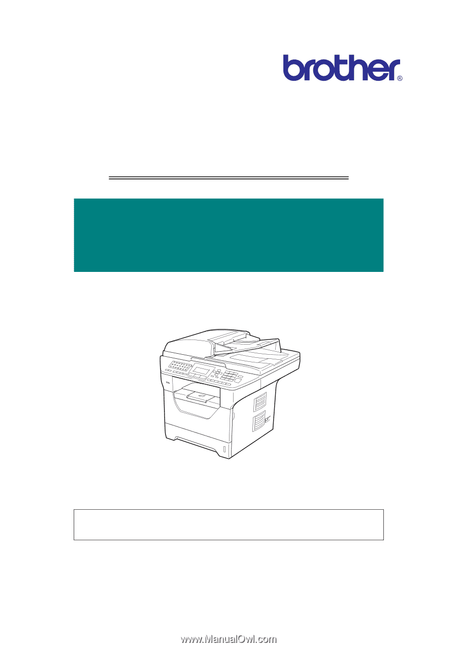
Confidential
Laser FAX/MFC
SERVICE MANUAL
Read this manual thoroughly before maintenance work.
Keep this manual in a convenient place for quick and easy reference at all times.
January 2009
SM-FAX105
MODEL:
DCP-8080DN/8085DN
MFC-8480DN/8880DN/8890DW