Brother International HS-5000 Service Manual
Brother International HS-5000 - Color Solid Ink Printer Manual
 |
UPC - 012502524298
View all Brother International HS-5000 manuals
Add to My Manuals
Save this manual to your list of manuals |
Brother International HS-5000 manual content summary:
- Brother International HS-5000 | Service Manual - Page 1
SERVICE MANUAL MODEL: HS-5000 / 5300 - Brother International HS-5000 | Service Manual - Page 2
any means without permission in writing from the publisher. Specifications are subject to change without notice. Trademarks: The brother logo is a registered trademark of Brother Industries, Ltd. Apple, the Apple Logo, and Macintosh are trademarks, registered in the United States and other countries - Brother International HS-5000 | Service Manual - Page 3
6. CONSUMABLES AND SERVICE ACCESSORIES 6.1 Brother Special Transparencies 6.2 Maintenance Paper Cassette 6.3 Ink 6.4 Print Head CHAPTER II THEORY OF OPERATION 1. ELECTRONICS 1.1 General Block Diagram 1.2 Configuration of Electronics 1.3 Main PCB 1.4 Driver - Brother International HS-5000 | Service Manual - Page 4
ASSY (1st Bin) 4.3 Second Sheet Feeder ASSY (2nd Bin) 4.5 Rear Cover ASSY (HS-5000 only) 4.6 Top Cover 4.7 Ink Case ASSY 4.8 Main Cover 4.9 Key Top 4.12 Output Tray ASSY 4.13 Maintenance Frame ASSY 4.14 Base Plate ASSY 4.15 Driver PCB ASSY 4.16 Main Frame ASSY 4.17 Power Supply PCB ASSY 4.18 Fan 80 - Brother International HS-5000 | Service Manual - Page 5
IV TROUBLE SHOOTING 1. INTRODUCTION 1.1 Initial Check 1.2 Basic Procedure 2. TROUBLE SHOOTING 2.1 Trouble Shooting Driver PCB Circuit Diagram (1/5) Appendix 10 Driver PCB Circuit Diagram (2/5) Appendix 11 Driver PCB Circuit Diagram (3/5) Appendix 12 Driver PCB Circuit Diagram (4/5) Appendix 13 Driver - Brother International HS-5000 | Service Manual - Page 6
LED 4.10.5 Alarm LED 4.10.6 Online Button 4.10.7 Reset Button 4.10.8 FF/Cont Button 4.10.9 Shift + Test Button 4.10.10 Shift + Clean Button 4.10.11 Test Print Mode 4.10.12 Reset and Hex Dump Print Mode 5. SAFETY INFORMATION 5.1 Ink Safety 6. CONSUMABLES AND SERVICE ACCESSORIES 6.1 Brother Special - Brother International HS-5000 | Service Manual - Page 7
The printer driver provides a Brother own color driver enables color matching between the monitor and printer and offers control of various color effects. It helps you to get fine color output. This printer also supports used. The factory setting of Power Save model and mode 2 are both OFF, however - Brother International HS-5000 | Service Manual - Page 8
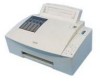
3. CONFIGURATION 3.1 Mechanics Manual feed slot Ink reservoir cover N Top cover Extension wire ,-- , -:.E?-- Output tray Fig. 1.1 Second sheet feeder (2nd bin) (HS-5300 only) First sheet feeder (1st bin) Control panel 1-2 - Brother International HS-5000 | Service Manual - Page 9
so!uoapa13 The configuration diagram is as shown below. MIO interface 11 (C2 Centronics interface Control PCB Paper eject sensor Driver PCB Switch panel Head Carriage PCB Encoder PW sensor Platen heater Media sensor Cam home position SW Maintenance PE SW PE sensor Option ROM SI M M ( - Brother International HS-5000 | Service Manual - Page 10
) TrueType-compatible soft-fonts for Windows 3.1/3.11/95 on the supplied disks Windows 3.1/3.11/95 driver, supporting Brother Native mode and bi-directional capability PCL5c, PCL5e with standard and BR-Script Level2 for option Bi-directional parallel 24MB standard 8MB on the Main PCB and 16MB on - Brother International HS-5000 | Service Manual - Page 11
Storage: 10 to 85% (without condensation) 4.5 Dimensions (W x H x D) and Weight HS-5000: 490 x 410 x 310mm (19.3 x 16.2 x 12.2 inches) HS-5300: 490 x 510 x 310mm (19.3 x 20 x 12.2 inches, when the output is closed.) Weight HS-5000: HS-5300: Approx. 12kg (27 lb.) Approx. 13kg (28.6 lb.) 1-5 - Brother International HS-5000 | Service Manual - Page 12
photocopiers or laser printers. Use Brother special transparencies which are designed for the HS-5000/5300 printers to obtain optimum print will not feed from the sheet feeder, use the manual feed slot and try again. There will be no paper transport problems in the printer for A5, B5, C4, Executive - Brother International HS-5000 | Service Manual - Page 13
100 sheets (80g/m2 ) 4.8 Paper (Recommended) • Plain paper Hammermill copyplus (201b) (in USA) Xerox Premier (80g/m2) (in Europe) • Special paper Brother special transparencies Letter size No. HSTRL A4 size No. HSTRA 4.9 Printable Area PR98064 A4 Letter Legal COM-10 Paper size (mm - Brother International HS-5000 | Service Manual - Page 14
4.10 Control Panel Alarm IN Manual r Filter Data mu Ink FF/ Cont Test Reset Clean Ready ■ On Line Paper Power N Fig. 1.6 4.10.1 up or cleaning the print head. The printer is ready to print. This LED blinks with the Alarm LED to indicate a paper error. See 3.3 Error Codes in Chapter 4. 1-8 - Brother International HS-5000 | Service Manual - Page 15
has printed, you need to press the FF/Cont button to print the remaining data. This LED blinks with the Alarm LED to indicate an ink empty error. 4.10.4 Manual LED The Manual LED indicates the current paper source. LED Off O Blinking 04-40 On • Printer status Sheet Feeder mode The printer is - Brother International HS-5000 | Service Manual - Page 16
manual feed in your application, the printer alerts you to load paper in the manual feed slot by blinking the Manual the Shift button starts head cleaning. If you see any problems on printouts, clean the print head and try again. print mode. The Alarm LED blinks to indicate that the first choice, Print Config - Brother International HS-5000 | Service Manual - Page 17
Press the FF/Cont button to perform the selected choice. LED Alarm Manual Data Choice User Reset Factory Reset Hex Dump print Function The printer data as hexadecimal values, so that you can check data errors and problems. To exit from this mode, press the Reset button or turn the printer off - Brother International HS-5000 | Service Manual - Page 18
: Do not induce vomiting. If necessary, get medical attention. INHALATION: Move into the fresh air. 6. CONSUMABLES AND SERVICE ACCESSORIES 6.1 Brother Special Transparencies Letter size No. HSTRL A4 size No. HSTRA 6.2 Maintenance Paper Cassette Maintenance paper cassette and 1 paper - Brother International HS-5000 | Service Manual - Page 19
1.1 General Block Diagram 1.2 Configuration of Electronics 1.3 Main PCB 1.3.1 Features 1.3.2 Image Processing 1.3.3 Print Head Control 1.3.4 Engine Control 1.4 Driver PCB 1.4.1 PA Motor Drive Circuit 1.4.2 Carriage Motor Drive Circuit 1.4.3 Solenoid Drive Circuit 1.4.4 Switch Panel Control Circuit - Brother International HS-5000 | Service Manual - Page 20
SW Panel Heater Driver Solenoid Driver Motor Driver P6 +52V P13 P14 P10 El P11 P21 P22 O P23 P5 O P24O P25El P7_ P8 P4 P2 CR PCB Head Encoder PW Sensor Platen Heater Quench Platen Thermistor Media Sensor Cam Home Position SW Maintenance PE SW PE Sensor Solenoid Solenoid HS-5300 only PA Motor - Brother International HS-5000 | Service Manual - Page 21
voltage, PS fan motor and fan motor. It also detects the amount of ink remaining, the maintenance PE and sends the data to the head driver. (2) Driver PCB Drives the PA and carriage motors, solenoids, LEDs on the switch panel, platen heater, head heater, ink remaining detection circuit, PS fan motor - Brother International HS-5000 | Service Manual - Page 22
ROM DRAM SIMM x2 Slot -o C) co IDT79R3051-20J (#31) Main CPU (#30 Program ROM MB87A133 (#28) ASIC 2 µPD784021 (#33) Engine CPU Driver Interface Paper Feed Motor Sensor Input Operator Panel LED Control > Fan Motor Control PS Fan Motor Control < Extension I/O Operator Panel Key Input - Brother International HS-5000 | Service Manual - Page 23
1.3.1. Features The circuit on the control PCB is classified into the following three sections. • Image processing Converts the image data received from the centronics parallel interface into the bit map. • Print head control Sends the bitmap data, which is converted from the image data, to the head - Brother International HS-5000 | Service Manual - Page 24
capacity of a SIMM for installing is recommended;: • 1 Mbyte HITACHI HB56D25632B-6A, -7A, MITSUBISHI MH25632BJ-7 • 2 Mbyte HITACHI HB56D51232B-6A, -7A MITSUBISHI MH51232BJ-7 • 4 Mbyte HITACHI HB56A132BV-7A, -7AL, -7B, -7BL MITSUBISHI MH1M32ADJ-7 • 8 Mbyte HITACHI HB56A232BT-7A, -7AL, -7B, -7BL - Brother International HS-5000 | Service Manual - Page 25
1.3.3 Print Head Control (1) ASIC 2 The MB87A133 is used as the ASIC to control the print head. The ASIC becomes the bus master instead of the main CPU during the print process and reads the converted image data from the DRAM based on the encoder signal and conditions sent from the main CPU and - Brother International HS-5000 | Service Manual - Page 26
the motor starts rotating and the PF_Hold signal high when it is in the hold mode. Main PCB i Engine CPU PF_A, PF_AN, PF_B, PF_BN Driver PCB +39/30V 0 > PA Motor Drive Circuit P4 Jet < ASIC3 PF_Hold Fig. 2.3 1.4.2 Carriage Motor Drive Circuit The carriage motor is a DC motor and its - Brother International HS-5000 | Service Manual - Page 27
rotate the paper feed roller for paper feeding. In the HS-5300, the solenoids are activated to rotate the paper feed roller (1st bin or 2nd bin) for paper feeding or to stop rotation of the regist roller. Engine CPU < Main PCB Jet > ASIC3 Driver PCB +25V P8 SOL_B SOL C Solenoid Drive SOL - Brother International HS-5000 | Service Manual - Page 28
platen. Main PCB i < Engine CPU > Jet ASIC3 SCLK SDATA SLATCH MSENA Driver PCB Shift Register HT_PPLATEN HT_PLATEN Heater Driver +52V ....ri o P10 • nP11 Platen Heater HT OHS HT_FE1 HT_FE2 HT BE Heater Driver Fig. 2.7 v CR PCB +52V 1 > Head Heater Main PCB Engine < CPU Jet - Brother International HS-5000 | Service Manual - Page 29
1.4.6 LOIS Circuit A thermistor is attached to the head ink tank for each color as an ink empty sensor. When a specified voltage level is applied to the thermistor, it heats up by itself. When the ink level in the ink tank is higher than the thermistor position, the ink absorbs the heat produced by - Brother International HS-5000 | Service Manual - Page 30
table below. FAN _ HIGH High Low Low FAN _ LOW Low High Low Rotation speed High Low Stop Fig. 2.10 Main PCB i Driver PCB +25V 0 Engine CPU FAN_HIGH FAN LOW Driver P6 Fan Motor Fig. 2.11 1.4.8 PS Fan Motor Drive Circuit The PS fan motor drive circuit controls the rotation of PS fan - Brother International HS-5000 | Service Manual - Page 31
for the print head and generates pulses to drive the head. Main PCB Driver PCB i Carriage Engine < CPU Jet > ASIC3 Head Driver CR PCB Head Fig. 2.13 1.5 CR PCB The CR PCB connects the driver PCB and the head on the carriage, the head heater, the encoder, the PW sensor, the tank heater - Brother International HS-5000 | Service Manual - Page 32
1.6 Control Panel PCB Three switches and five LEDs are mounted on this PCB. Main PCB Driver PCB i Control Panel PCB Engine CPU Panel PCB Fig. 2.15 - Brother International HS-5000 | Service Manual - Page 33
1.7 Power Supply Unit The power supply unit generates several DC power sources from the AC power source. The DC power sources generated by the power unit are +5V, +25V, +52V, and +39/30V. The DC CHG signal switches the output between +39V and +30V. The power supply unit contains the AC heater ON/OFF - Brother International HS-5000 | Service Manual - Page 34
-ri csT N "-1 •••1 Paper separation rollor ASSY 2 r rzzz4 Main frame 0 Pre heater -,_ Main heater M-platen Q-platen Air duct Base plate Carriage Eject tray Eject chute ASSY Driver PCB - Brother International HS-5000 | Service Manual - Page 35
2.2 Print Head 2.2.1 Functions of the Print Head The print head used in this printer is an on-demand type using a piezoelectric ceramic actuator to fire ink. The print head is composed of four Front ends each of which has 128 nozzles and one Back end combined with the Front ends. Each Front end - Brother International HS-5000 | Service Manual - Page 36
2.2.2 Structure of the Print Head (1) Front end Each Front end has 128 nozzles arranged in zigzags and fires the ink supplied from the Back end in drops. (2) Back end The Back end is connected to four (four-color) Front ends and supplies the hot melt ink in each color to the respective Front end. - Brother International HS-5000 | Service Manual - Page 37
2.3 Ink Holder and Ink Supply Mechanism In this printer, ink is supplied from a solid ink block which is set into the ink case and fed to the head through the ink supply mechanism. (1) Refilling of solid ink blocks • Opening the ink silo cover enables setting of solid ink blocks in the ink case. • - Brother International HS-5000 | Service Manual - Page 38
Ink melting tank Carriage operation O Ink supply area Carriage home position Carriage Rib for changing correct of carriage Rib for changing correct of carriage 0 0 Fig. N2.30 Pull lever Rib for ink dropping on a carriage Cam home position switch 0 0 Direction of rotation O O Wait condition - Brother International HS-5000 | Service Manual - Page 39
00 0 0 Direction of rotation 0 0 (OHS SW: OFF) Fig. N2.32 00 Direction of rotation O O. Starting of pushing ink Fig. N2.33 11-20 - Brother International HS-5000 | Service Manual - Page 40
00 Direction of rotation 0 O. Dropping ink Fig. N2.34 V 00 0 Direction of rotation 0 0 Fig. N2.35 11-21 - Brother International HS-5000 | Service Manual - Page 41
qiii O 0 Direction of rotation O O Wait condition (OHS SW: ON) Fig. N2.36 Cam Carriage operation Iii.... Gear Rib for changing correct of carriage Carriage home position Fig. 2.18 11-22 Clutch to be connected - Brother International HS-5000 | Service Manual - Page 42
of the head unit using special paper. 2.4.2 Structure of the Maintenance Unit (1) Maintenance unit frame The maintenance frame supports the mechanisms (2)-(7) below and secures them to the frame. (2) Maintenance cartridge The maintenance cartridge is a consumable part and composed of the following - Brother International HS-5000 | Service Manual - Page 43
the disc cam to feed air to the tube. It is constructed to prevent negative pressure from being produced. (6) Capping mechanism The capping mechanism supports a capping block with a rubber seal using a spring plate. When the head unit moves to the right end position, it is connected to a hole made - Brother International HS-5000 | Service Manual - Page 44
2.5 Sensors The printer has the following sensors. Paper empty sensor Paper regist solenoid 2nd PF solenoid Media sensor o )i\ Pre-heat platen thermistor Heat platen thermistor Quentch platen thermistor 1st PF solenoid Encoder Maintenance paper empty switch . Paper eject Cover open switch - Brother International HS-5000 | Service Manual - Page 45
The paper delivery sensor is placed at the down stream of the PA lower roller and detects paper jamming during paper transportation. (6) Maintenance paper empty switch (MPE) The maintenance paper empty switch is placed in the maintenance mechanism and detects the maintenance paper empty. (7) Cover - Brother International HS-5000 | Service Manual - Page 46
pulley /" ' 7_ /--------- / IIIIIIIIIIIIIIII111111111111111111 .IIIIIIIIIIIIIIIIIIIII LJLILJLI .441 4 Idle pulley Timing belt Front Fig. 2.21 Carriage guide shaft The carriage is supported by the guide shaft and guide plate installed on the main frame so that it freely moves in the horizontal - Brother International HS-5000 | Service Manual - Page 47
driven by a specified number of pulses to drive the regist roller to feed the paper to the print start position. (HS-5000) f^ Sheet feeder 2nd sheet feeder (HS-5300) Hook Solenoid A 1st sheet feeder O 0 Spring Separation roller gear Pinch roller PF roller gear 0 0 PA motor Fig. 2.22 Hook - Brother International HS-5000 | Service Manual - Page 48
-0 (D co tD wspetpew uogags! as pue uogeie v. I rt fit 11111111 Regist sensor actuator 2 Separation roller Regist sensor actuator 1 Separation pad 0 Photo sensor - Brother International HS-5000 | Service Manual - Page 49
. PA upper roller ASSY PA motor m 0 0 m Timing belt Fig. 2.25 PA lower roller ASSY Feed roller Fan Media sensor PA upper roller M-platen 0 .i. - Q-platen Q-platen supporting spring PA lower roller 0 Eject tray Air duct Fig. 2.26 11-30 - Brother International HS-5000 | Service Manual - Page 50
transparency on OHPs. The pressure to hold the paper or OHP stay in close contact with the platen is produced by the Qplaten support spring. M-platen \ Air duct )x. Platen ground spring Fig. 2.27 Q-platen • Functions (1) As a chute for paper transportation. (2) Heats paper to fix the ink onto - Brother International HS-5000 | Service Manual - Page 51
4.4.1 2nd Bin Frame ASSY 4.4.2 Fan Motor 25 ASSY 4.5 Rear Cover ASSY (HS-5000 only) 4.5.1 Rear Cover 4.5.2 Fan Motor 15 4.6 Top Cover 4.7 Ink 4.13.3 MPE Switch ASSY 4.13.4 Connecting Rubber ASSY 4.14 Base Plate ASSY 4.15 Driver PCB ASSY 4.16 Main Frame ASSY III-1 III-3 III-6 III-6 III-6 III-6 III - Brother International HS-5000 | Service Manual - Page 52
4.16.1 PE Sensor ASSY, Regist Sensor Actuator 2 and 3 and Regist Sensor Actuator Spring 4.17 Power Supply PCB ASSY 4.18 Fan 80 4.19 PA Motor ASSY 4.20 Main Frame ASSY 4.20.1 Solenoid PH 1 ASSY and PH 2 ASSY 4.20.2 Cam Home Position SW ASSY 4.20.3 Cover Open SW ASSY 4.21 Print Head 4.22 Upper Nip - Brother International HS-5000 | Service Manual - Page 53
CHAPTER III DISASSEMBLY AND REASSEMBLY 1. SAFETY PRECAUTIONS To prevent the creation of secondary problems by mishandling, be careful to observe the following precautions during maintenance work. (1) Always turn off the power switch before replacing parts or units. When accessing - Brother International HS-5000 | Service Manual - Page 54
(4) When using soldering irons or other heat-generating tools, take care not to damage parts such as the wiring, PCBs and covers. (5) Before handling the PCBs, touch a metal portion of the equipment to discharge the static electricity in your body, or electronic parts or components may be damaged. - Brother International HS-5000 | Service Manual - Page 55
fixing plate Head Paper width sensor ASSY Encoder PCB ASSY T fence guide Relay PCB cover CR motor ASSY CRI pulley holder CR beam Belt connector PCB ASSY, MID connector PCB holder Main PCB plate Heat sink Driver PCB CR PCB AC electrode support C ASSY Screw, pan (s/p washer) M3X32 Taptite, pan B M3X6 - Brother International HS-5000 | Service Manual - Page 56
DR Screw, pan M3X5 2 Fan motor 25 (HS-5300 only) 2 bin frame (HS-5300 only) Chute 1 Taptite, cup B M3X8 2 Taptite, bind B M4X10 2 Taptite, cup S M3X6 3 Pre-Baffle ASSY Taptite, cup S M3X6 2 Harness film Taptite, cup B M3X8 1 Side guide gear (1st bin) Taptite, cup B M3X6 1 Taptite - Brother International HS-5000 | Service Manual - Page 57
PCB ASSY 9.1 Panel PCB ASSY 9.2 SW Panel Holder 15. Base Plate ASSY 16. Driver PCB ASSY 16. Main Frame ASSY 16.1 - PE Sensor ASSY - Regist Sensor Actuator Cable 26. CR Beam ASSY 27. Lower Nip Holder ASSY *1 HS-5300 only *2 HS-5000 only 28 Air Duct ASSY 29 Upper PA Roller ASSY 30 Lower PA - Brother International HS-5000 | Service Manual - Page 58
4. DISASSEMBLING AND REASSEMBLING PROCEDURE Note: Reassembly is the reverse ofDisassembly unless otherwise stated. Please refer to Notes relating to Reassembly information. 4.1 Extension Wire (1) Push both end of the Extension wire and remove it. Ejection chute Eject tray ASSY Fig. - Brother International HS-5000 | Service Manual - Page 59
the printer body. Note: After reassembling, check that the left and right holes in the First sheet feeder are securely mounted on the positioning bosses. First sheet feeder ASSY Positioning boss N N \ z ,.i,' ------_ Second sheet feeder ASSY 10 ....•.., 1.7 ----___ I t '-.% C) - C Main - Brother International HS-5000 | Service Manual - Page 60
remove it from the 2nd bin frame ASSY. Note: After reassembling, check that the left and right holes in the Second sheet feeder are securely mounted on the positioning bosses. 2nd sheet feeder ASSY Positioning boss Q / 2nd bin frame ASSY Fig. 4.6 III-8 - Brother International HS-5000 | Service Manual - Page 61
4.4 Second Sheet Feeder Frame ASSY 4.4.1 2nd Bin Frame ASSY (1) Remove the screw and the harness film and then disconnect the PS fan motor connector. 2nd bin frame ASSY Taptite, cup B M3X10 Harness film PS fan connector Fig. 4.7 (2) Remove the two screws and disassemble the 2nd bin - Brother International HS-5000 | Service Manual - Page 62
4.4.2 Fan Motor 25 ASSY (1) Remove two screws securing the Motor holder. (2) Remove the Fan motor 25 ASSY from the Motor holder. Fan motor 25 ASSY a c Fig. 4.9 Motor holder Taptite, cup B M3X8 III-10 - Brother International HS-5000 | Service Manual - Page 63
4.5 Rear Cover ASSY (HS-5000 only) 4.5.1 Rear Cover (1) Remove the screw and take off the Rear cover ASSY while releasing the hooks. 4.5.2 Fan Motor 15 Fig. 4.10 (1) Remove two screws securing the Fan motor 15. ""lc Taptite, cup B M4X10 0 r- V Fig. 4.11 Taptite, - Brother International HS-5000 | Service Manual - Page 64
4.6 Top Cover (1) Hold the Top cover ASSY with the sheet feeder removed, open it to its stop position and then press it further in the same direction to bend the left and right hooks to remove it. Top cover Main cover ASSY / -----. , I Fig. 4.12 Fit the - Brother International HS-5000 | Service Manual - Page 65
4.7 Ink Case ASSY (1) Release the hook of the Ink case ASSY to open it, then lift it upwards slightly just before it reaches its stop position to remove. Ink case ASSY Main cover ASSY r Hook Fig. 4.14 (2) Open the Upper ink case, lift it upwards slightly just before it reaches its - Brother International HS-5000 | Service Manual - Page 66
4.8 Main Cover (1) Remove the four screws and two screws securing the Main cover ASSY. (2) Hold the left and right lower edges of the Main cover ASSY and lift it upwards to remove. Taptite, bind B M4X10 - Brother International HS-5000 | Service Manual - Page 67
Key top co) • ' 14/ O SWP harness ASSY Earth cable Panel PCB ASSY SW panel holder CR guide bar earth plate R Fig. 4.18 Note: Check that the harness is securely connected to the connector. 4.9.2 SW Panel Holder (1) Remove the Encoder strip from the Encoder strip - Brother International HS-5000 | Service Manual - Page 68
it is contaminated by the dust, blow it out by a air blush. (2) When reassembling, check the orientation of the Encoder strip. See below. Encoder strip guide Carriage ASSY ,sf7 . aorA- fzr- a Encoder strip --4-40-3' C) 1 4\ Fig. 4.20 III-16 - Brother International HS-5000 | Service Manual - Page 69
PR98064 (3) As shown in the illustration above, insert the right end of the Encoder strip into the Encoder strip guide on the Carriage ASSY and then pass it through the Encoder strip guide. (4) Hook the right hand end of the Encoder strip onto the Encoder strip spring at the right hand of the - Brother International HS-5000 | Service Manual - Page 70
4.11 Main PCB ASSY 4.11.1 Main PCB ASSY (1) Remove the five screws at the locations marked with V on the Rear panel and pull the Main PCB ASSY toward you. PCB rail ti Main frame ASSY Taptite, cup S M3X6 Main PCB ASSY Rear panel Taptite, cup S M3X6 Fig. 4.22 Note: Insert - Brother International HS-5000 | Service Manual - Page 71
into the bent part of the Rear panel and sliding the MID rails toward the Rear panel, press the MID rail until the hook is secured. 4.11.3 MIO Connector PCB ASSY (1) Remove the two screws from the bottom of the MID connector PCB to remove the MID connector PCB ASSY - Brother International HS-5000 | Service Manual - Page 72
4.11.4 Rear Panel and PCB Angle Plate (1) Remove the two screws from the Rear panel and the two screws securing the parallel I/F connector. (2) Remove the two screws (one for each PCB angle bracket) from the bottom of the Main PCB. PCB angle bracket Rear panel . - Brother International HS-5000 | Service Manual - Page 73
. (1) Reassemble the ROM PCB on the PCB spacer so that it is engaged with the connector. Note: Make sure that the ROM PCB is securely engaged with the connector. ROM PCB Main PCB PCB spacer Fig. 4.26 4.11.6 MIO PCB ASSY (Option) (1) Make sure that the power is turned - Brother International HS-5000 | Service Manual - Page 74
4.12 Output Tray ASSY (1) Fully pull the Output tray toward you, lift it upwards to release the two hooks from the Ejection chute, and pull out the Output tray ASSY together with the Ejection chute. Ejection chute At 1 r \ -i Hook Main frame ASSY Output tray ASSY Fig. 4.28 - Brother International HS-5000 | Service Manual - Page 75
hit the Link lever 1, which is a white plastic lever, into the Main frame ASSY. (6) Remove the connector of the PE switch ASSY from the Driver PCB ASSY. Main frame ASSY Link lever Taptite, bind B M3X10 Maintenance frame ASSY 4 I Connector of the PE switch ASSY Hook Fig. 4.31 Note - Brother International HS-5000 | Service Manual - Page 76
ASSY. Pin Cylinder ASSY Cam gear 33 Fig. 4.33 The pins of the Cylinder ASSY run the grooves, which are the grayed lines. Note: Securely insert the pins of the Cylinder ASSY into the grooves of the Cam gear 33. Check that the Cam gear 33 rotates full circle. III - Brother International HS-5000 | Service Manual - Page 77
4.13.3 MPE Switch ASSY (1) Remove the Maintenance switch lock spring. (2) Unlock the Maintenance switch lock by pressing the hook in the boss. (3) Remove the PE switch ASSY. Remove the harness from the hook on the bottom of the Maintenance frame ASSY. Maintenance switch lock Hook N - Brother International HS-5000 | Service Manual - Page 78
4.14 Base Plate ASSY 5 (1) Remove the harness and the Purge tube from the harness clamps. Remove the two screw fixing the earth cables. PR98064 o CR drive PCB N )('' ' .1d Earth cable L„e '7NN'i I, N Screw, pan (S/R washer)M3X5 Harness ) Fig. 4.36 ----,----- Main frame - Brother International HS-5000 | Service Manual - Page 79
(3) Remove the three screws and the Joint plate. Remove the screw securing the Grounding wire. Remove the screw securing the Inlet holder. Taptite, cup S M3X6 Joint plate .") Main frame ASSY Taptite, bind S M4X8 Grounding wire Screw, bind M3.5X8 Inlet holder Fig. 4.38 (4) Turn - Brother International HS-5000 | Service Manual - Page 80
Screw, bind M3.5X8 !;) N Base plate Main frame ASSY Fig. 4.41 (1) Position the Base plate on the two bosses on the Main frame ASSY. (2) Secure the Base plate with 13 screws. (3) Turn over the Main frame ASSY. (4) Press the Inlet holder and slide the hook of the Inlet holder until - Brother International HS-5000 | Service Manual - Page 81
harness clamp and clamp the harness with the right harness clamp. (9) Fit the Shield plate CRM and secure with two screws. (10) Fit the earth cables and secure with two screw. (11) Refit the Maintenance cassette. 4.15 Driver PCB ASSY (1) Remove all the harness connectors from the - Brother International HS-5000 | Service Manual - Page 82
FFC cables from the FFC connectors. FFC connector Driver PCB ASSY 4, FFC cable Fig. 4.43 (1) Insert the FFC cables into the connectors and hold the Driver PCB ASSY upside down. (2) Insert the cables into slot 1 and 2 securely. (3) Position the two bosses on the Main frame - Brother International HS-5000 | Service Manual - Page 83
connector from the Driver PCB ASSY. Regist sensor actuator 2 Regist sensor actuator 3 \. - 7- 00 PE sensor ASSY Fig. 4.45 Regist sensor actuator spring Note 1: After reassembly, check that the Regist sensor actuators 2 and 3 rotate smoothly. Note 2: For HS-5300, mount the Regist - Brother International HS-5000 | Service Manual - Page 84
ti . , Groove Shield plate Shield plate DR ., "*.......f. .. 6, • Driver PCB ASSY Handset PS ASSY r , - J.---t 1 17 Power supply harness the two bosses on the Shield plate. (2) Secure the Power supply PCB with five screws. (3) Securely connect the four harnesses to the connectors. (4) - Brother International HS-5000 | Service Manual - Page 85
(6) Securely connect the Power supply harness ASSY VH and PH to the Driver PCB. Screw, bind M4X8 4 Shield plate Screw, pan M3X5 N Screw, bind M4X8 Power supply PCB ASSY Screw, bind M4X8 i Shield plate DR Fig. 4.48 Note: - Brother International HS-5000 | Service Manual - Page 86
4.18 Fan 80 (1) Remove the two springs which secure the Air duct. (2) Remove three screws from the Fan holder and lift the Fan holder up. (3) Remove two screws from the Fan motor. Spring Taptite, - Brother International HS-5000 | Service Manual - Page 87
(1) Slightly loosen the two screws securing the PA motor ASSY and remove the PA spring Fig. 4.51 (2) Remove the two screws and the PA belt support plate. Main frame ASSY PA upper roller ASSY PA belt support plate \ / Taptite, cup M3X6 O PA lower roller ASSY --_________J - Brother International HS-5000 | Service Manual - Page 88
bind B M3X10 Co) qqk C C 141./ C PA roller gear plate Taptite, bind B M3X10 PA motor holder weld ASSY Fig. 4.53 (4) Remove the two screws securing the PA motor ASSY and remove it. (5) Remove the two screws, then remove the High-damping rubber. (6) Remove the Ferrite core. High-damping rubber - Brother International HS-5000 | Service Manual - Page 89
Note 2: Secure the PA belt support plate at a position where the two positions shown in the in the release mode.) Put the project part of the Bearing A at the opposite side of the PA belt support plate and mount the plate at a position where it is not in contact with the project part of the Bearing - Brother International HS-5000 | Service Manual - Page 90
together with the Actuator C and the Solenoid spring. Gear 40/54 Solenoid PH 1 ASSY Gear 45 arm O . Cr' r/cte7 V r) 6 0 a 5 Gear 20 Taiyo HS Fig. 4.56 Gear Z30 ASSY Solenoid spring Solenoid PH 1 ASSY Actuator C Actuator B O Fig. 4.57 (6) Remove the Actuator A. (7) Remove the Actuator - Brother International HS-5000 | Service Manual - Page 91
■ HS-5300 Remove the Gear 20 Taiyo HS. Remove the Idle gears Z25 and Z45. Remove the Gear Z30 ASSY. Remove the Gear 45 arm. Remove the Gear 40/54. PR98064 Solenoid PH 1 ASSY Gear Z 25 Gear Z 45 0 Gear 40/54 0 Gear Z 30 ASSY Gear 45 arm 6 Solenoid PH 2 ASSY (*1) Gear 20 Taiyo HS Solenoid - Brother International HS-5000 | Service Manual - Page 92
(7) Remove the Solenoid PH 2 ASSY (*1), Actuator 1 and the Solenoid spring at the same time. Actuator A Actuator 1 Solenoid PH 2 ASSY (*1) (Red cable) (White cable) Fig. 4.61 0 Solenoi. spring Solenoid PH 2 ASSY (*2) (8) Remove the Actuator A and Solenoid PH 2 ASSY (*2) at the same time. Actuator - Brother International HS-5000 | Service Manual - Page 93
4.20.2 Cam Home Position SW ASSY (1) Loosen the screw (do NOT remove it) from the CR I pulley holder ASSY through the hole on the right front side of the Main frame ASSY. Push the CR I pulley holder ASSY toward the Carriage motor and remove the Timing belt from the pulley of the - Brother International HS-5000 | Service Manual - Page 94
If you go further disassembly flow from this page, the head gap adjustment is necessary after reassembly See section 5.1 Head Gap in this chapter. 4.21 Print Head (1) Move the Carriage ASSY to the center of the Main frame ASSY. (2) Remove the two screws and release the hooks at both - Brother International HS-5000 | Service Manual - Page 95
position of the printer. (5) Remove the screw from the left hand side of the AC electrode support C ASSY. (6) Remove the connectors from the AC electrodes support C ASSY. AC electrode support C ASSY Taptite, bind B M2.6X6 Taptite, bind B M2.6X6 \\\ Main frame ASSY Fig. 4.67 Connector (7) Lift - Brother International HS-5000 | Service Manual - Page 96
reference surface. (2) Tighten the screws (A) first, then (B) while pushing down the Head ASSY using a screw driver. Refer to fig. 4.69 for the screws. Remove the Gap spacer. (Di Screw driver Carriage ASSY Head ASSY Reference surfaces of the window O r Reference surfaces of the window Window - Brother International HS-5000 | Service Manual - Page 97
sure that the left flange of the AC electrode support C ASSY holds the FFC cables in place. AC electrode support C ASSY 7 Carriage ASSY FFC cable Fig. , check that the front end heater harness and the PW sensor harness are secured by the hooks on the Head ASSY as shown in the enlarged figure. - Brother International HS-5000 | Service Manual - Page 98
CR PCB cover Insert it into the center slit Encoder harness • Carriage ASSY Fig. 4.73 111-46 - Brother International HS-5000 | Service Manual - Page 99
4.22 Upper Nip Plate Unit PR98064 4.22.1 Upper Nip Plate Unit Caution!: Do not loosen the two screws securing the Carriage guide plate. The Carriage guide plate has been fixed by using an adjustment tool. (See section 5.2 Head Gap and Parallel Alignment in this chapter). (1) Move - Brother International HS-5000 | Service Manual - Page 100
4.22.2 Baffle Plate Caution: The Baffle plate is the very thin metal part. Be careful with the sharp edge while handle it. (1) Carefully lift up the left hand side of the Baffle plate and release from the bosses. Slide it horizontally being careful not to bend it. Baffle plate D - Brother International HS-5000 | Service Manual - Page 101
4.22.3 Nip Release Lever (1) Remove four Upper nip springs. (2) Remove the Nip release lever by sliding the Nip release shaft horizontally while releasing the hook of the Nip release lever. Nip release lever L-.-- r Hook ' Upper nip plate unit Fig. 4.76 Nip release shaft Nip spring - Brother International HS-5000 | Service Manual - Page 102
the Nip release cam. (2) Push the Nip release shaft until the hook is securely located in the groove on the shaft. (3) Fit the springs Nip release cam Nip release shaft Nip release lever Upper nip support plate ••• - Upper nip roller holder Fig. 4.78 Nip spring Note: Locate the correct - Brother International HS-5000 | Service Manual - Page 103
4.22.4 Upper Nip Roller ASSY (1) Remove the Upper nip roller ASSY from the Upper nip roller holder. Nip roller upper B Nip roller upper A Nip roller upper B Upper nip roller holder Fig. 4.80 Note: Ensure the Nip roller upper B is correctly located III-51 - Brother International HS-5000 | Service Manual - Page 104
Upper sensor holder after releasing the hook. Upper sensor holder Guide ...----"" 0O C Guide Fig. 4.81 Upper nip plate unit (2) Remove the MED the hook of the Upper sensor holder. Guide Upper sensor holder ri MED sensor PT380 ASSY 2 Guide ---- ---- 71 4- MED sensor PT380 ASSY - Brother International HS-5000 | Service Manual - Page 105
hooks so that it is properly located onto the hooks. Hook the Upper sensor holder onto the Upper nip plate unit by matching the four guides (Refer to fig. 4.82) and then press it downwards. (4) Put the harness into the hole of the Main frame ASSY and attach the core with - Brother International HS-5000 | Service Manual - Page 106
4.23 Main Frame ASSY 4.23.1 DR Board Cover Remove the DR board cover, which is located at the bottom of the Main frame ASSY, by releasing the two hooks. Hook DR board cover It I t Main frame ASSY t Fig. 4.84 4.23.2 Pressure Roller (1) Remove the Pressure roller by - Brother International HS-5000 | Service Manual - Page 107
(1) Put the two Pressure rollers into the Pressure roller shaft and secure it to the Main frame ASSY with the hook. (2) Check that the Pressure rollers rotate smoothly. 4.23.3 Chute 1 ASSY Caution: The Chute 1ASSY is - Brother International HS-5000 | Service Manual - Page 108
(2) Slide the Feed roller H to the left hand side. (3) Remove the PF gear by releasing the hook and remove the PF shaft bearin g. Main frame ASSY PF shaft bearing PF gear Fig. 4.88 (4) Slide the Feed roller H further more till the end of the shaft comes out from the hole of the Main frame ASSY. - Brother International HS-5000 | Service Manual - Page 109
groove on the MED sensor GL380 ASSY of the Lower sensor holder. Carefully run the harness through the hole in the Main frame ASSY and secure it to the Math frame ASSY with the hook so that it is not caught in the Main frame ASSY. Check that the Lower sensor - Brother International HS-5000 | Service Manual - Page 110
4.24 Carriage ASSY (1) Remove the Oil holder cover and the Oil holder from the Carriage ASSY. Oil holder cover Hook CR guide bar Oil holder Carriage ASSY Fig. 4.92 (2) Push the latch hook on the right hand side towards the right and remove the FFC pressure bottom - Brother International HS-5000 | Service Manual - Page 111
on the left hand side of the Main frame ASSY, is severely adjusted and secured with those screws at the factory site to have parallelism between the CR guide bar and the PA roller. (8) Pull out the CR guide bar from the hole in the right hand side of the Main frame ASSY - Brother International HS-5000 | Service Manual - Page 112
(9) Remove the screw A and loosen the screw from the CR idle pulley holder ASSY through the hole on the right front side of the Main frame ASSY. Push the CR idle pulley holder ASSY toward the Carriage motor and remove the Timing belt from the pulley of the Carriage motor. Then remove the Carriage - Brother International HS-5000 | Service Manual - Page 113
the top of the Carriage ASSY. Remove the screw and the Encoder PCB ASSY. Encoder strip guide Taptite, bind 2.6X6 Encoder PCB ASSY 0 Taptite, bind 2.6X6 Fig. 4.98 Carriage ASSY (12) Release the two hooks and remove the PWS cover on the - Brother International HS-5000 | Service Manual - Page 114
sure that the line C and the line D are aligned When tightening the screw, securely hold the PCB so that it does not move. < View from the bottom of the CR guide plate. Make sure that the CR guide plate is held by the rib and the CR sub upper guide. Rib (A) CR sub upper guide CR guide plate - Brother International HS-5000 | Service Manual - Page 115
4.25 FFC Cable (1) Remove the FFC cable cap by releasing the hook from the bottom of from the Main frame ASSY. (2) Remove the FFC cable from the hook on the Main frame ASSY. (3) Remove the FFC cable from the FFC pressure bottom. FFC cable Main frame ASSY L------' LL---- FFC cable - Brother International HS-5000 | Service Manual - Page 116
the FFC cable is folded as below. 0 Fig. 4.104 Note 3: When connecting the FFC cable to the Carriage ASSY, check that the FFC cable is secured by the two hooks on the left hand end of the Carriage ASSY as shown below. FFC cable ... s Hook Carriage ASSY 0 4 -L-11 \ Hook Fig. 4.105 - Brother International HS-5000 | Service Manual - Page 117
4.26 CR Beam ASSY (1) Remove the Shield plate CRM. (2) Remove the five screws and carefully remove the Carriage beam ASSY so that the motor harness is not caught in the Main frame ASSY. Taptite, cup B M3X6 Taptite, cup B M3X6 Carriage beam ASSY Shield plate CRM . . ) 0 Main frame - Brother International HS-5000 | Service Manual - Page 118
4.27 Lower Nip Holder ASSY Caution: The Lower nip roller spring B is the thin metal part. Be careful with the sharp edge. (1) Remove all of the Lower nip roller spring and the Lower nip holder ASSY A, B and C. Lower nip holder C ASSY 0 Lower nip holder A ASSY Lower nip roller - Brother International HS-5000 | Service Manual - Page 119
(3) Remove the two screw and the Q-platen ASSY. (4) Remove the two screw and the M-platen ASSY. Note: During reassembly, carefully run the Pre-heater ASSY, the Main heater ASSY and the Q-platen ASSY through the holes in the Main frame ASSY so that they are not caught in the Main - Brother International HS-5000 | Service Manual - Page 120
4.30 Lower PA Roller ASSY (1) Release the hook of the Maintenance gear and then remove the Lower PA roller ASSY from the Main frame ASSY while pushing the Paper empty actuator. (2) Remove the Bearing A and then the Rower PA roller. (3) Remove the PA roller gear plate. (4) Remove - Brother International HS-5000 | Service Manual - Page 121
the Print head is replaced, conduct Head Drive Voltage Adjustment (See section 5.3). If the Head gap is not correct, loosen the screw securing the Gap lever arm. 6> Head .",...„.. 7/,,,. .7.-- Carriage Thickness gauge Fig. 5.1 (3) Insert the thickness gauge between the Print head and the Platen - Brother International HS-5000 | Service Manual - Page 122
and move the Carriage to the center of the Main frame. (4) Fit the Head gap gauges so they are positioned from the CR guide bar to the CR guide plate. Make sure the bars of the Head gap gauge touch inside of the Main frame. -111-111- I-I-0 00 0 0 , - 111.111.1.111.111 - Brother International HS-5000 | Service Manual - Page 123
gauge B Screw Dial gauge D Fig. 5.5 (6) Adjust the parallelism between the CR guide plate and the Platen by using a special wrench. Tighten the screws to secure the CR guide plate. The dial gauge A and B should read around "30". Secure the screw for the CR guide plate. • 0 • Fig. 5.6 III-71 - Brother International HS-5000 | Service Manual - Page 124
read around "30" and if the accuracy in the table below is achieved, secure the screw for the Gap lever arm. If not, return to (6) of (6) of 5.2 Head Gap and Parallel Adjustment and re-adjust the parallelism between the CR guide plate and the Platen. The dial gauge A and B should read in the range - Brother International HS-5000 | Service Manual - Page 125
then 300 dpi as the voltage for 300 dpi is made by adding a voltage onto the 600 dpi voltage. Screw driver Fig. 5.9 5.4 Offset, TOF and LF Adjustment Variable register 300 dpi Variable register 600 dpi Head Rank A B TOF, LF and nozzle alignment by using the support tool provided separately. III-73 - Brother International HS-5000 | Service Manual - Page 126
6. LUBRICATION 5 Apply the following lubricants to the lubrication points as illustrated below. PR98064 Lubricant amount Lubricant type (Manufacturer) Molykote EM-30L (Dow Corming) Synteso Pro AA2 PE3302-A00O0 (NOK) Floil 946P (Kanto Kasei) Half of a ricesized pinch of grease (3 mm3) Rice- - Brother International HS-5000 | Service Manual - Page 127
[2] Carriage ASSY Oil holder cover [3] Upper Nip Plate Unit (EMI 0 8 Oil holder P2 III-75 - Brother International HS-5000 | Service Manual - Page 128
[4] Changeover Lever 0 [5] CR Beam ASSY (EMI EM1 [6] Maintenance frame ASSY (KS1) 0 Idle pulley 0 0 4 111-76 - Brother International HS-5000 | Service Manual - Page 129
[7] Gear Train 0 0 0 0 0 GED 0 0 0 0 0 ED - Brother International HS-5000 | Service Manual - Page 130
The following cleaning kitis supplied with the printer. ( Clean Stick Cleanthe printer interior when the platen or rollers are stained by ink due to some problem such as a paper jam. You will need to clean out the spilt ink and remove any small pieces of paper remaining inside the printer. III - Brother International HS-5000 | Service Manual - Page 131
(1) Turn the printer power off. (2) Wait around 30 minutes after power off to allow the printer to cool down. (3) Open the top cover. Then open the inside cover. (4) Dampen the cleaning stick or wipers with the IPA(Isopropyl Alcohol)(90% or higher alcoholity) or the denatured alcohol(90% or higher - Brother International HS-5000 | Service Manual - Page 132
(7) Remove any small pieces of paper remaining in the printer interior. 4 O 41* 4 (8) To clean the rollers, wipe them with a cleaning stick. The rollers can be freed from the printer for cleaning by pulling the holders toward you. ►AA 111, bl /* * 401 • . . Warning!: NEVER touch the interior - Brother International HS-5000 | Service Manual - Page 133
8. PACKING Carton Ink Pad Power supply cord Pad Tray extension Extension wire User's manual Floppy disks Maintenance cassette Pad Pad HS-5000 HS-5300 Fig. 3.104 Carton 111-81 - Brother International HS-5000 | Service Manual - Page 134
CONTENTS 1. INTRODUCTION 1.1 Initial Check 1.2 Basic Procedure 2. TROUBLE SHOOTING 2.1 Trouble Shooting Procedure 2.1.1 Malfunctions 2.1.2 Print-image Related 3. INSPECTION MODE 3.1 Extended Functions 3.1.1 Self Printing Mode 3.1.2 Reset and Hex Dump Mode 3.2 Hidden Functions 3.2.1 Printer Setting - Brother International HS-5000 | Service Manual - Page 135
CHAPTER IV TROUBLE SHOOTING 1. INTRODUCTION 1.1 Initial Check If a malfunction or incorrect print appears, make is being used. (If the paper is too thin, or tends to curl, paper jams or paper feed problems may occur, or prints may be blurred.) 2) The print paper is damp. [If so, use fresh paper - Brother International HS-5000 | Service Manual - Page 136
TROUBLESHOOTING 2.1 Troubleshooting voltage is not supplied at the outlet. Plug the power cord securely into the outlet. If the fuse blows again immediately after replacing ? Turn the power switch OFF and disconnect the P17 connector (Driver PCB). Turn the power back on and measure the voltage between - Brother International HS-5000 | Service Manual - Page 137
cause Connection failure of connector P2. Step , Check 1 Are the connectors P2 and P3 on the driver PCB securely connected? , Result Remedy NO Connect them securely. Connection failure of connector P3. Carriage motor 2 Disconnect the connector P2 NO Replace the carriage from the - Brother International HS-5000 | Service Manual - Page 138
in the table below? Result NO YES NO Remedy Connect it securely. Replace the fan motor. Replace the driver PCB. Replace the Main PCB. P6-1 and P6-2 Approx. 25V (7) Fan 15 ASSY (for HS-5000) or Fan 25 ASSY (for HS-5300) does not rotate. Possible cause Connection failure of connector P19. Fan - Brother International HS-5000 | Service Manual - Page 139
-5000: Connection failure of connector P7. Step 1 Check Is (Are) the connector(s) P7 (and P8) on the driver PCB securely connected? Result NO Remedy Connect it (them) securely. HS-5300: Connection failure of connector P7 and P8. Paper pick-up 2 Disconnect connector P7 (and NO Replace the - Brother International HS-5000 | Service Manual - Page 140
failure Step , Check _ Result , Remedy 1 Is the connector P10 on the NO Connect it securely. driver PCB securely connected? 2 Remove connector P10 from YES Replace the M-platen the driver PCB. ASSY. Measure the resistance between the connector pins of the heater (P10-2 and P10-3) with - Brother International HS-5000 | Service Manual - Page 141
from its nozzles. - Replace the print head. - Replace the driver PCB. - Replace the power supply PCB. - Adjust the head gap with the gap lever. (If the problem persists, adjust the gap of the CR guide plate or the guide bar.) Random missing dots _ - _ White horizontal streaks I J - Perform the - Brother International HS-5000 | Service Manual - Page 142
strength goes down. b. Color become brighter. - Adjust the head gap with the gap adjust lever. (If the problem persists, adjust the gap of the CR guide plate or the guide bar.) - Use flesh paper. - Perform the head cleaning operation several times. - Check that the maintenance paper is correctly - Brother International HS-5000 | Service Manual - Page 143
reset, it is necessary to reset by turning off the power switch or pressing the reset switch to quit the HEX dump mode. 1 ALARM LED blinking Online 'Jr MANUAL LED blinking Online 'Jr DATA LED blinking Online 'Jr READY LED blinking Online FF/Cont_ ► User Reset FF/Cont_ ► Factory Reset FF/Cont - Brother International HS-5000 | Service Manual - Page 144
the FF/Cont switch, the selected setting function will be executed. After being executed, the printer will return to the ready status. 1 ALARM LED blinking Online 1 MANUAL LED blinking Online 1 DATA LED blinking Online I READY LED blinking Online FF/Cont FF/Cont FF/Cont FF/Cont ► NV-RAM User - Brother International HS-5000 | Service Manual - Page 145
hidden functions are assigned to the respective LED. By pressing the FF/Cont switch, the selected self printing will be executed. 1 ALARM LED blinking Online 1 MANUAL LED blinking Online 1 DATA LED blinking Online I READY LED blinking Online FF/Cont FF/Cont FF/Cont FF/Cont ► Print Config - Brother International HS-5000 | Service Manual - Page 146
switch, the selected self printing will be executed. 1 ALARM LED blinking Online 1 MANUAL LED blinking Online 1 DATA LED blinking Online I READY LED blinking Online FF/Cont FF/Cont FF/Cont FF/Cont ► Nozzle Check Pattern ► HS Check - Brother International HS-5000 | Service Manual - Page 147
Mode] The respective LED indicates the status of the following sensors. SENSOR Cover Sensor Maintenance Paper Paper Feeding Sensor : Paper Ejection Sensor : LED Alarm LED Manual LED Data LED Ready LED It is possible to perform the above tests repeatedly and it is necessary to reset the printer by - Brother International HS-5000 | Service Manual - Page 148
the status of the following switches. SWITCH FF/Cont Reset Online LED Manual LED Data LED Ready LED It is possible to perform the above tests the LED. SWITCH FF/Cont Reset FEEDER 1st sheet feeder 2nd sheet feeder (HS-5300 only) It is possible to perform the above test repeatedly and it is - Brother International HS-5000 | Service Manual - Page 149
following hidden functions are assigned to the respective LED. By pressing the FF/Cont switch, the selected test function will be executed. 1 ALARM LED blinking Online 1 MANUAL LED blinking Online 1 DATA LED blinking Online I READY LED blinking Online FF/Cont FF/Cont FF/Cont FF/Cont ► Ink Supply - Brother International HS-5000 | Service Manual - Page 150
[Fan Motor Rotation Test Mode] (Not neccessary for the service) Changes the rotation of the fan motor according to the pressing of following switches. SWITCH FF/Co nt Reset Online MODE High Low Stop It - Brother International HS-5000 | Service Manual - Page 151
A SIMM or the MIO board is not installed correctly. (An error print sheet is printed out.) Service calls Alarm Manual Data Ready LED LED LED LED ROM Error O RAM Error X NVRAM Error O Controller Service Error X ASIC Error O Engine ROM Error X Engine RAM Error O Engine Program Error - Brother International HS-5000 | Service Manual - Page 152
LED INDICATING THE ERROR Example: ROM Error Alarm LED O X O X O Manual LED O X X X O Data LED O X X X O Ready LED O X X X O Power LED O X X X O A lapse of time O : ON X : OFF IV-18 - Brother International HS-5000 | Service Manual - Page 153
617) Appendix 8 Main PCB Circuit Diagram (717) Appendix 9 Driver PCB Circuit Diagram (1/5) Appendix 10 Driver PCB Circuit Diagram (2/5) Appendix 11 Driver PCB Circuit Diagram (3/5) Appendix 12 Driver PCB Circuit Diagram (4/5) Appendix 13 Driver PCB Circuit Diagram (5/5) Appendix 14 Panel PCB Circuit - Brother International HS-5000 | Service Manual - Page 154
SLOT) CAM HOME POSITION SW MAINTENANCE PE SW PE SENSOR DRIVER PCB I II I P5 P24 P25 MEDIA SENSOR I II I P23 P22 P20 P1 SWITCH PANEL P11 PLATEN HEATER P10 P21 QUENCH PLATEN THERMISTOR P1 P8 r SOLENOID P7 [ SOLENOID HS-5300 only P13 P14 P6 [ FAN MOTOR P4 [ O PA MOTOR P19 - Brother International HS-5000 | Service Manual - Page 155
Appendix 2. Main PCB Circuit Diagram (117) 2 A 10 11 12 A AD(31 00)(601> Data C31:00] #3I IDT7993051-20J vac, g VCC VCC 2: VCC 3 VCC . 42 , 50 VCC VCC CSO C76 C65 C60 C5S . 57 VCC . 66 VCC coo C70 C64 C57 iiiiiiiiii CGS a 80 VCC VCC TTTTTTTTTT.. V55 104 X 10 , P VSS VSS , - Brother International HS-5000 | Service Manual - Page 156
VSYNCN ENVDON MIDVSYN SO 172 170 --- VSERQN VOFFN nCBD (0S-03E) nMIOVsync (05-02E) C41 104 4 #5 AL900 SS ALSOB SS ALSOB 12 #5 R126 R51 R12G Modell(4MByte) 0 0 0 0 Model218MByte) x x s o OV (401)(03-02C) (04-01H) COE-O1.8, (OS-04F) O .02.01-01E, COS-02F) .03,03-028) 005-040> (404) OM - Brother International HS-5000 | Service Manual - Page 157
Appendix 4. Main PCB Circuit Diagram (317) 2 8 10 11 I 12 - Brother International HS-5000 | Service Manual - Page 158
Appendix 5. Main PCB Circuit Diagram (4/7) 032-11D) WOE (02-I2C) nIRASO (02-12C) nIRAS1 032-I1D) nWE 3 q R26 33 .11 AL51034 nWWE 8 #36 .37 #38 #36 hodell x o x o Model2 0 0 0 0 a (02-11D) nCAS C3:0] a 031-11. Data C31:00] (02-IIC) nXRAS[3.01 (02-05F) MAI20.00] nC4.64) nICASO nCAS1 13 nCAS - Brother International HS-5000 | Service Manual - Page 159
Appendix 6. Main PCB Circuit Diagram (517) I I 4 (03-11G3 RMA CIO :00] 022-05F) MA I20 '60] M In P6 / Zg:i`00 RMA02 RMA04 RMA05 RMA07 / :r V7U,i 6553( 100 31= le s -44 6652 sl - 13 100 K 4 71W ng "`"", e7 1231 >C7 1391 >A13 El) BB 1241 )CB gel >A9 9] )09 [251 1411 / RMA09 RMA10 sl „ - Brother International HS-5000 | Service Manual - Page 160
PCs !Z: PCG -rEv RB£1 10K 0V0 R121 0 SP7 R88 R121 Modell o x Modell x o (01-11A) ADC31:00] HDFIRKOC HDFIRKOD 141 HDFIRK1C HDFIRK1D 05E) nHdDrvRst 9> CR_Ol_Ena 4. CR_02_Ena CR 03 Ena CR:04:Ena Driver PS-2 Ai 61> LED Alarm LED:Manual C1, LED Data A2' LED:Ready 62 LED Power C2 A3 - Brother International HS-5000 | Service Manual - Page 161
(66-09C) PIO_Pulse (06-09C1 PWMDir (06-110 SenLED On 006-09A) nLED_PotTler C06-09A, nLED_Ready (06-09A) HEED Data (06-09A) nLED Alarm C06-09A, HEED-Manual R115 00 P01 P02 16 17 ;E5P` P07 47 P1O/POM0 P1 4 r.121/PA=2/SCK2 P13/RxD2/512 51 P14/TxD2/S02 52 P15 - Brother International HS-5000 | Service Manual - Page 162
Appendix 9. Driver PCB Circuit 2 4 SPD OE -IOC, PANEL LED DATA >P20 LED_READY >P213 LED MANUAL >P20 LED_POWER >P28 4 LED_ALARM 20 SW_ONLINE >P20 +511 P2O T C76 J R37 > 120X , (X - I0C) , 4 AC_HT_CTRL- COVER SW (m -I0C1 MBA MODEL 1 R22 - Brother International HS-5000 | Service Manual - Page 163
Appendix 10. Driver PCB Circuit Diagram (2/5) 2 3 4 10 11 12 425V 412V0 A - Brother International HS-5000 | Service Manual - Page 164
Appendix 11. Driver PCB Circuit Diagram (315) 2 10 11 12 +3981+30 A FLFUSE 10 175 PTZ3. HD_YO_C C(34-08C) HD_YILD (04-1091 HDYI_C (04-10C) HDYL_D 3 I MODEL I MHSA 057 HDEl /A i +258 (11:-104) DCCHNCN OS I I MH9A MODEL 5 1 - Brother International HS-5000 | Service Manual - Page 165
Appendix 12. Driver PCB Circuit Diagram (4/5) 10 11 12 A (03- 09A) OFFVDD Rg:; 8.2K R1,1; i` - Brother International HS-5000 | Service Manual - Page 166
Appendix 13. Driver PCB Circuit Diagram (5/5) 3 4 6 7 10 II 12 FFC A 9552 ( 0V L. VSS2 -01ST .5+11 R141 YOSORCE 004-1017 CN -110 HT_BE 5 MODEL IMH9A 025 027 SD 898 L11 DRL-015T Y ISORCE C04-120) - IIC) HTFEI R107 4.7K 031 MH9A MODEL R102 220 034 FEIRTN OK -06C) 1-52V C L ' - Brother International HS-5000 | Service Manual - Page 167
LED_POWER > 4 LED_ALARM >5 SW_ONL I NE - Brother International HS-5000 | Service Manual - Page 168
Appendix 15. CR Drive PCB Circuit Diagram • 1 S6C A CISORCE 2 POV 2 P12 COSORCE 2 POV 2 2 KOSORCE P 2 2 POV 2 KISORCE;P12 +52V 2 BERTN 21 2 +52V 2 OHSRTN PS2 sc.cog2 THR_BE P02 CISORCE .00 COSORCE DCOD K050RCE .043 L1 BL M21A05 K 1SORCE .09 +522 BERTN PE - 09C0 OHSRTN Cm -11F) 002 THR_BE C.
-
 1
1 -
 2
2 -
 3
3 -
 4
4 -
 5
5 -
 6
6 -
 7
7 -
8
-
9
-
10
-
11
-
12
-
13
-
14
-
15
-
16
-
17
-
18
-
19
-
20
-
21
-
22
-
23
-
24
-
25
-
26
-
27
-
28
-
29
-
30
-
31
-
32
-
33
-
34
-
35
-
36
-
37
-
38
-
39
-
40
-
41
-
42
-
43
-
44
-
45
-
46
-
47
-
48
-
49
-
50
-
51
-
52
-
53
-
54
-
55
-
56
-
57
-
58
-
59
-
60
-
61
-
62
-
63
-
64
-
65
-
66
-
67
-
68
-
69
-
70
-
71
-
72
-
73
-
74
-
75
-
76
-
77
-
78
-
79
-
80
-
81
-
82
-
83
-
84
-
85
-
86
-
87
-
88
-
89
-
90
-
91
-
92
-
93
-
94
-
95
-
96
-
97
-
98
-
99
-
100
-
101
-
102
-
103
-
104
-
105
-
106
-
107
-
108
-
109
-
110
-
111
-
112
-
113
-
114
-
115
-
116
-
117
-
118
-
119
-
120
-
121
-
122
-
123
-
124
-
125
-
126
-
127
-
128
-
129
-
130
-
131
-
132
-
133
-
134
-
135
-
136
-
137
-
138
-
139
-
140
-
141
-
142
-
143
-
144
-
145
-
146
-
147
-
148
-
149
-
150
-
151
-
152
-
153
-
154
-
155
-
156
-
157
-
158
-
159
-
160
-
161
-
162
-
163
-
164
-
165
-
166
-
167
-
168
 |
 |

SERVICE
MANUAL
MODEL:
HS
-5000
/
5300