Brother International KM-430B Network Users Manual - English
Brother International KM-430B Manual
 |
View all Brother International KM-430B manuals
Add to My Manuals
Save this manual to your list of manuals |
Brother International KM-430B manual content summary:
- Brother International KM-430B | Network Users Manual - English - Page 1
SERVICE MANUAL FOR BROTHER MODEL L.K3-B430 -49- • BROTHER • pe• 411.• • a • • j poi BROTHER INDUSTRIES, LTD. NAGOYA, JAPAN - Brother International KM-430B | Network Users Manual - English - Page 2
CONTENTS SPECIFICATIONS (MOTOR PULLEYAND SPEED) C STANDARDTENSION C MECHANISM E Needle bar, thread take-up lever, lower shaft, shuttle mechanisms 3 • Clutch mechanism 4 • Power work clamp lifter and thread wiper mechanisms 5 O Feed mechanism 6 El Thread trimmer mechanism 7 E Thread - Brother International KM-430B | Network Users Manual - English - Page 3
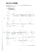
,7SPECIFICATIONSD The table below shows the sub-classes of the LK3-B430 type high speed bar tacking machine. BROTHER INDUSTRIES, LTD. LK3-B430 - MADE! APAN z Sub -class -1 -2 -3 -4 -5 Main uses Decorative stitching Ordinary clothes Denim 11 Ordinary clothes 4. . ,i:i.,.!,.L.'4,./ :A- - Brother International KM-430B | Network Users Manual - English - Page 4
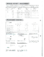
MOTOR PULLEY AND SPEED The LK3-B430 High Speed Bar Tacking Machine is capable of high speed sewing at a maximum speed of 2,300 rpm. When changing the speed, refer to the table below and select a speed suitable to the work. In case of using chemical thread, operate the machine at 1,800 rpm to - Brother International KM-430B | Network Users Manual - English - Page 5
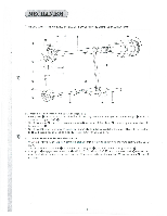
moved up and down via needle bar crank rod 0. 3. Needle bar 0, which is gripped by needle bar clamp 0, is guided by needle bar bushing U 0, needle bar bushing D and needle bar guide slide block m' smoothly run up and down. 0 00 (2) Lower Shaft and Shuttle Mechanism 4. When pulley 0 turns in the - Brother International KM-430B | Network Users Manual - English - Page 6
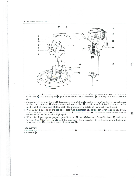
[2 CLUTCH MECHANISM 0 0 A 0- 0 o- 0- 0 0 0 8 0 0 0 --" 0 I . When start le\ er 0 operates in the arrow direction, the low speed part ® of ball presser plate 0, which is fixed to clutch lever 0 N is connecting rod 0, gets in line with the center of steel ball 0 to convey the power to - Brother International KM-430B | Network Users Manual - English - Page 7
to thread wiper link 0 via thread wiper shafts as fulcrum, and actuates thread wiper e, which is connected to thread wiper arm 0, via thread wiper arm support Q as fulcrum. - Brother International KM-430B | Network Users Manual - English - Page 8
to tack width feed lever 0, similarly rocks. 3. Tack width lever 0 is connected to tack width regulator lever 0 with nut so that it moves feed guide back and forth about tack width lever shaft ® as fulcrum. (2) Tack Length Mechanism 4. Roller ID fits in the groove on the underside of feed cam - Brother International KM-430B | Network Users Manual - English - Page 9
[J THREAD TRIMMER MECHANISM \_0 0 00 0 O __y 0 • --- I . When power cam rotates one half of a turn in the arrow direction, roller 0 in contact with the cam part ® of 0 power cam 0 is pushed down so that the motion is conveyed via thread trimming link 0 to cam lever Q through driving shaft Q as - Brother International KM-430B | Network Users Manual - English - Page 10
position, tension release pin rides on the cam part © to release tension discs (C) and simultaneously conveys the motion to thread take-up lever 49 via guide stud ® which is fixed to guide bearing thereby feeding the necessary length of thread for starting the next sewing. 0 - Brother International KM-430B | Network Users Manual - English - Page 11
, and remove the V-belt. -0 9. Return the machine head. It). Remove the chain. 2 PRESSER ARM I. Needle bar thread guide 0 Remove screw 0, needle 0, and then needle bar ( thread guide 0. 2. Presser arm 0 Remove presser arm 0 by taking off bolts 0 and washers 0 at right and left. 3. Feed - Brother International KM-430B | Network Users Manual - English - Page 12
exercising care not to drop the pin out of it. 3. Thread take-up lever 0 Remove two screws 0 and 0, and then thread 0 take-up lever 0. 4. Guide stud Remove it by turning it with a screwdriver. 5. Tension release bar plate 0 Remove two screws e and washers Q), and then tension relase bar plate 0. El - Brother International KM-430B | Network Users Manual - English - Page 13
7 FEED 1. Raise the machine head. 2. Loosen screw 0, and pull out wich Q from tack length feed lever 0. 3. Tack length feed lever 0 Loosen bolt 0, remove tack length feed lever shaft 0 together with washer 0, and remove tack length feed lever 0 by moving it in the arrow direction, exercising care - Brother International KM-430B | Network Users Manual - English - Page 14
THREAD TRIMMER I. While turning the pulley, operate the emergency sotp lever until the knife cam lever claw dropps into the recess of the knife cam. 2. Raise the machine head. 3. Thread trimming arm A 0 Remove E-shaped stop ring e, loosen screw 0, and remove thread trimming arm A 0. 4. Thread - Brother International KM-430B | Network Users Manual - English - Page 15
ASSEMBLING PROCEDURE PULLEY 1. Pulley assembly 0 (1) Fit spring 0 over the upper shaft, push pulley assembly 0 onto the upper shaft toward the arm, fit three washers 0 onto the upper shaft, and then insert key 0 into the keyway. (2) Install clutch plate 0 in such a way that the keyway is in line - Brother International KM-430B | Network Users Manual - English - Page 16
5. Raise the machine head. 6. Thread trimming arm B (D Insert it from above the bed. •- 7. Thread trimming arm A ® Fit the pin into the tip of connecting rod 0, slide thread trimming arm A onto the lower end of ®, thread trimming arm B and snap stop ring on. 8. Needle plate assembly e Fit the - Brother International KM-430B | Network Users Manual - English - Page 17
,m 5. Tension release lever 0. Insert the tip of it into the arm, put washer on tension release lever shaft 0, and tighten screw The tension release lever Q can easily be installed if the crank rod is shifted to the left as viewed from the rear of the machine by turning the pulley. 6. Clutch - Brother International KM-430B | Network Users Manual - English - Page 18
0 0 0 0 0 .0 FEED I. Raise the machine head. 2. Feed cam With the stopper in contact with the stop cam (stop 0 position), fit the cam lever roller into the cam groove, and install feed cam 0 with washer and bolt 0 in such a way that the mark 0 of the feed cam meets the mark O of the bed. In - Brother International KM-430B | Network Users Manual - English - Page 19
0 Connect it to the tip of the tension release bar, and temporarily fasten it with two each screws Q and washers 0. 2. Guide stud 0 Install it on the thread take-up guide bearing, using a screwdriver. 3. Thread take-up lever Install it with two screws Q and 0. 4. Sub-tension Temporarily fasten it to - Brother International KM-430B | Network Users Manual - English - Page 20
, adjust it so the second lowest reference line ® meets the lower end of the needle bar bushing. (2) After this adjustment, fit needle bar thread guide €) onto the needle bar, insert needle a) into place with its long groove facing the front, and fasten it with screw Q. (3) Raise the machine head - Brother International KM-430B | Network Users Manual - English - Page 21
7. Clearance between needle and shuttle hook Turn the pulley so that the point of the shuttle hook meets the center of the needle. Loosen screw and turn eccentric shaft m so that the clearance between the point of the shuttle hook and the needle is 0.01 to 0.08 mm. 0 8. Clearance between needle and - Brother International KM-430B | Network Users Manual - English - Page 22
Oa DISC CLEARANCES OF MAIN AND SUB TENSIONS I. Sub-tension 0 Loosen screw 0, and move the sub-tension in or out so that the tension disc presser will make a clearance of 0.5 to 1.0 mm at the machine stop position. 2. Main tension 0 Loosen two screws 0, and move tension release bar plate 0 to the - Brother International KM-430B | Network Users Manual - English - Page 23
it START LEVER POSITIONING 1. Start rod Temporarily tighten eccentric screw Q with nut at the machine stop position. 0 2. Start lever 0 Turn the pulley by hand until stop cam 0 comes to 5 mm before the stop position. Turn eccentric screw 0 so that roller shaft Q disengages at this position. - Brother International KM-430B | Network Users Manual - English - Page 24
0 0 O z 0- 1 BROTHER fio CNC 0 -0 0 2. Face plate Fasten face plate 0 with three screws 0. 3. Shuttle race cover Install it with two each screws 0 and washers 0. 4. Bed cover R (1) ®. Place washer ® - Brother International KM-430B | Network Users Manual - English - Page 25
__ADJUSTING PROCEDURE [I1- NEEDLE BAR 1. Needle bar height adjustment 6 7-* 0 Turn the pulley to lower the needle bar to its lowest position. Then loosen screw 0 and move the needle bar up or down so that the uppermost reference line ® of the needle bar is flush with the lower end of the needle bar - Brother International KM-430B | Network Users Manual - English - Page 26
4. Needle and shuttle hook clearance adjustment 0. 01-0. 08mm O OTurn the pulley to bring the top of the shuttle hook into line with the center of the needle. Then loosen screw() and turn the eccentric shaft Q so that the clearance between the needle and the top of the shuttle hook is 0.01 to 0.08 - Brother International KM-430B | Network Users Manual - English - Page 27
1 Tack width adjustment Turn the pulley by hand until the needle shown the Reference Needle Position on the preceding page (which varies with the specifications) falls into the needle hole. Loosen bolt 0, and move the presser arm forward or back so that the needle falls in the center of the work - Brother International KM-430B | Network Users Manual - English - Page 28
0 , 0 I ot 0 VERTICAL SHAFT 1. Roller holder lever position adjustment 0 0 O- 0 With the machine at the stop position (roller 0 riding on the projected part on the periphery of the feed cam), loosen bolt 0 anLl move roller holder 0 to adjust the clearance between clutch cam lever roller and - Brother International KM-430B | Network Users Manual - English - Page 29
[41, CLUTCH AND BRAKE 1. Stopper adjustment With the machine at the stop position, loosen nut and adjust nut 0 so that the bottom of stopper 0 meets the end of clutch lever 0. r Meet 2. Clutch lever position adjustment 0 0 6 2-` 0. 5mm WC4":lAtv-r. hil)45e114- efv- 0 - ith clutch cam - Brother International KM-430B | Network Users Manual - English - Page 30
will not slip. * If, after years of use, the pulley slips even after the above-mentioned adjustment, refer to the pulley disassembly instructions on Page 12, remove one washer, and make a re-adjustment. 4. Clutch cam timing adjustment - -0 90° 0- -0 ----0 Loosen bolt and turn clutch cam 0 so - Brother International KM-430B | Network Users Manual - English - Page 31
6. Start safe lever adjustment Loosen two bolts m and move start safe lever 6) up or down so that the clearance between it and periphery of the power cam is 3 mm at the machine stop position. • 3 mm e 7. Start stopper position adjustment Loosen two bolts and move stopper up or down so that, when - Brother International KM-430B | Network Users Manual - English - Page 32
9. Clutch lever spring pressure adjustment If the clutch lever operates so hard that the clutch will not positively fall upon sewing the last stitch, reconnect clutch lever spring el to the second position m of the clutch lever spring hook. 10. Brake spring pressure adjustment If a very heavy - Brother International KM-430B | Network Users Manual - English - Page 33
0 0 0 00 '5 POWER WORK CLAMP LIFTER 1. Power drive lever adjustment (I) Check that the slot 0 of the power cam is in line with the center of roller Q at the machine stop position (with the work clamp up). If not, insert a screwdriver into the slot, and push the power cam so that it is aligned with - Brother International KM-430B | Network Users Manual - English - Page 34
[6] THREAD TRIMMER 1. Movable knife position Er, /-- -- 0 0 ( I ) With knife cam lever roller 0 on the periphery of the knife cam, loosen screw 0 and move movable knife 0 so that its corner meets the mark 0 (outside) of the needle plate. - -0 eE, (2) When the power pulley is turned little by - Brother International KM-430B | Network Users Manual - English - Page 35
sewn. ( I ) With the machine in operation, loosen screw 0, and move guide shaft to the right or left. The smaller the stroke, the better will be adjusting the thread take-up lever stroke, adjust it so that the center of guide shaft 0 will always be within the mark range. 2. Main tension disc - Brother International KM-430B | Network Users Manual - English - Page 36
i THREAD WIPER 1. Thread wiper height adjustment Loosen screw 0, and move thread wiper arm supporter 0 up or down so that the clearance between the wiper and the tip of the needle will be 2 mm when the wiper passes under the - Brother International KM-430B | Network Users Manual - English - Page 37
PROCEDURE 1 FROM ORDINARY STITCHES TO KNITTED STITCHES • Necessary replacement parts • Feed cam 0 Change gear C 0 Change gear W 0 Work clamps L, R 0 O Needle Feed guide 0 Needle hole plate 0 ( 11$111#11111/111111 0 c (Procedure) When changing the number of stitches, be sure to do so at the - Brother International KM-430B | Network Users Manual - English - Page 38
hole plate 0 with two screws 7. Temporarily fasten feed plate Q with two screws e• • 8. Fit work clamps L, R 0 in place, and fasten work e- clamp guide brackets A ID and B Q) with six screws lir). 9. Tighten two screws 0, making sure that when the • 0 work clamp is lowered, it does not - Brother International KM-430B | Network Users Manual - English - Page 39
Q LIST OF REPLACEMENT PARTS Uses Name of part Feed cam ttk Ordinary clothes Feed cam S (42 stitches) 152727-0-01 Feed cam S (28 stitches) 153054-0-0 I Feed cam K (28 stitches) 153343-0-01 Feed cam K (42 stitches) 153344-0-01 Change gear C Change gear 42C (42 stitches) 152722-0-00 Change gear 28C - Brother International KM-430B | Network Users Manual - English - Page 40
Uses [Name of part Needle hole plate Ordinary clothes Needle hole plate B (inner diameter 2.2) 152909-0-01 Needle Needle DP X 5 (#I6) 107415-0-16 Denim Knitted clothes Needle hole plate C (inner diameter 2.2 with cross-shaped groove) 152910-0-01 Needle hole plate D (inner diameter 2.5 with - Brother International KM-430B | Network Users Manual - English - Page 41
TROUBLESHOOTING CHART Trouble Cause Check Remedy Page Clutch lever does not turn up enough. Clearance between stop cam and stopper Adjust clutch lever position 27 Ball presser plate - Brother International KM-430B | Network Users Manual - English - Page 42
Trouble Cause Check Remedy ' Page No high speed operation High-speed belt tension is not enough High-speed belt tension High-speed pulley is slipping in - Brother International KM-430B | Network Users Manual - English - Page 43
Trouble Cause Check Remedy Page Start position is incorrect. Feed eam position is wrong Feed cam position Fault• start Start stopper position is wrong. Ball presser - Brother International KM-430B | Network Users Manual - English - Page 44
Trouble Cause Check Remedy Pare No high speed operation High-speed belt tension is not enough High-speed pulley is slipping in high speed operation High- - Brother International KM-430B | Network Users Manual - English - Page 45
Trouble Cause Check Upper thread breaks. Lower thread breaks. Lower thread snaps. Stitches skip. Needle breaks. Upper thread tension is too great. Upper thread tension Adjust - Brother International KM-430B | Network Users Manual - English - Page 46
Trouble Cause Check Remedy Upper thread is not cut. Fixed knife is blunt. guide position. Adjust needle bar stroke. Movable knife does not scoop upper thread due to final stitch skipping. Final stitch skipping. Movable knife position is wrong. Movable knife position Refer to instructions
-
 1
1 -
 2
2 -
 3
3 -
 4
4 -
 5
5 -
 6
6 -
 7
7 -
8
-
9
-
10
-
11
-
12
-
13
-
14
-
15
-
16
-
17
-
18
-
19
-
20
-
21
-
22
-
23
-
24
-
25
-
26
-
27
-
28
-
29
-
30
-
31
-
32
-
33
-
34
-
35
-
36
-
37
-
38
-
39
-
40
-
41
-
42
-
43
-
44
-
45
-
46
 |
 |

SERVICE
MANUAL
FOR
BROTHER
MODEL
L.K3-B430
-49-
•
BROTHER
•
•
pe•
•
411
.
•
j
•
a
poi
BROTHER
INDUSTRIES,
LTD.
NAGOYA,
JAPAN