Brother International BES-100E BE-100 Workbook - English - Page 54
Inserting a Polygon Hole - windows 7
 |
View all Brother International BES-100E manuals
Add to My Manuals
Save this manual to your list of manuals |
Page 54 highlights
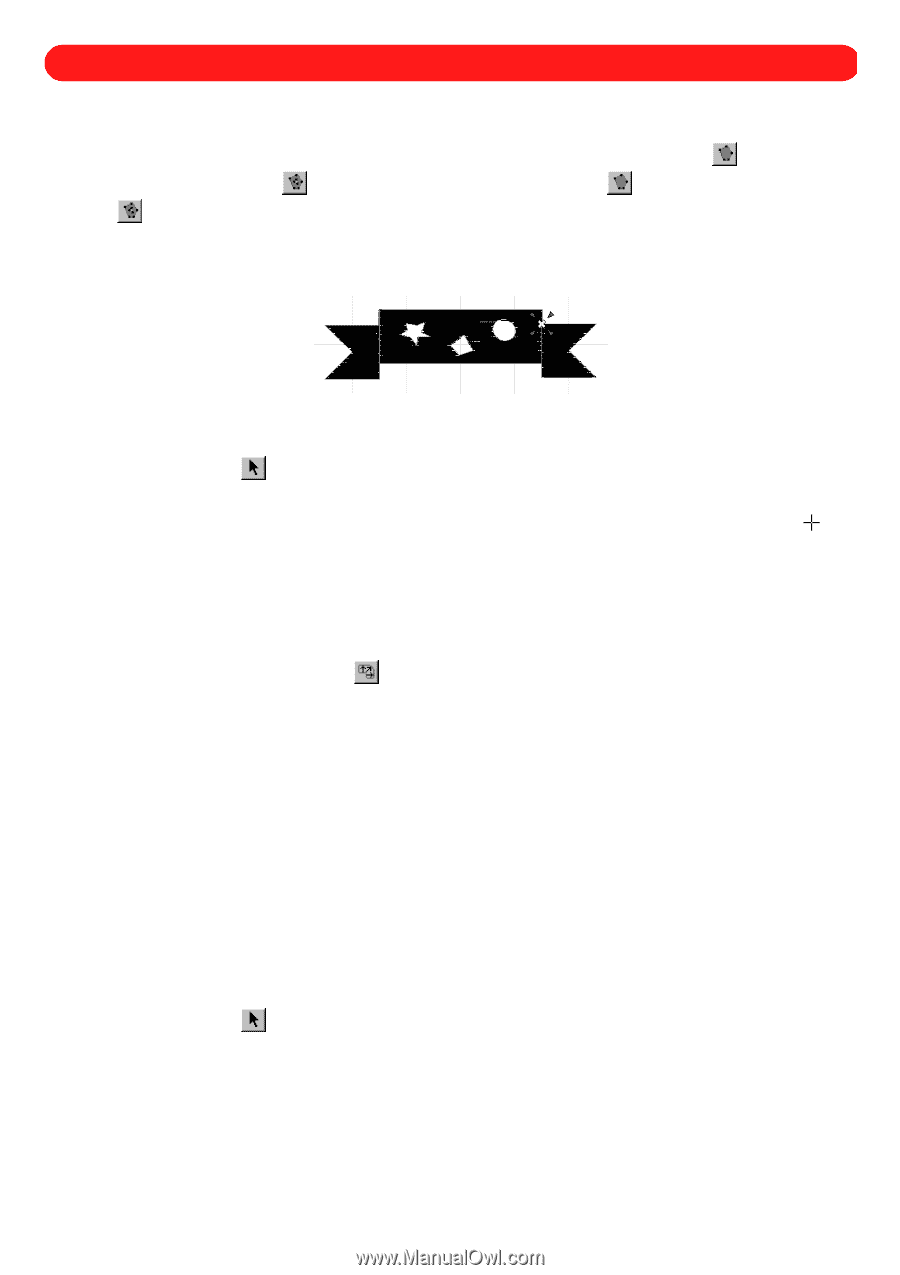
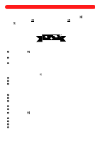
Chapter 21: Inserting a Polygon Hole After a polygon is created, a hole can be inserted to remove some of the stitching from a specific area, creating a "donut hole". NOTE: For more information about creating polygons, see Using the Simple Polygon tool ( ) and Using the Complex Polygon tool ( ) in chapter 20. The Simple Polygon tool ( ) and the Complex Polygon tool ( ) are available in the digitizing level of the software. Figure 88 To cut a hole out of a polygon: 1 Using the Move tool ( ), select the polygon from which you wish to cut out a hole. "Dancing ants" (mov- ing dashes) appear around the polygon. 2 On the Shape drop-down menu, click Insert Polygon Hole. The pointer changes to large crosshairs ( ) when it is moved into the design area. 3 Click within the polygon to trace the hole outline. NOTE: Do not overlap the hole outlines or click outside the edge of the polygon; otherwise, the fill stitches will not be generated. Adding a hole to a polygon removes any stitch directions that may have been entered using the Polygon Stitch Direction tool ( ) in the Stock toolbar. 4 Right-click once to close the hole. 5 Repeat steps 3 and 4 until all desired hole outlines are specified. 6 Right-click again to cut out the holes from the polygon. s Example To cut holes from a sample design in the "Shapes" file (from the "Sample" folder): 1 On the File drop-down menu, click Open. The Open dialog box appears. 2 In the Files of type drop-down list, select "BES Files (*.bdf)". 3 In the Look in drop-down list, select the "BES" folder, and then in the list below it, double-click the "Sample" folder. 4 In the Look in list, select the "Shapes" file. 5 Click the Open button. The "Shapes" file is opened. 6 Using the Move tool ( ), drag the pointer to select only the simple black banner at the lower-left corner of the design. "Dancing ants" appear around the banner. 7 On the Edit drop-down menu, click Copy. A copy of the banner is placed on the Windows clipboard. 8 On the File drop-down menu, click New. The Design Info dialog box appears. 9 Specify the desired settings for the new file. 0 Click the OK button. A new blank design area appears. 51
-
 1
1 -
2
-
3
-
4
-
5
-
6
-
7
-
8
-
9
-
10
-
11
-
12
-
13
-
14
-
15
-
16
-
17
-
18
-
19
-
20
-
21
-
22
-
23
-
24
-
25
-
26
-
27
-
28
-
29
-
30
-
31
-
32
-
33
-
34
-
35
-
36
-
37
-
38
-
39
-
40
-
41
-
42
-
43
-
44
-
45
-
46
-
47
-
48
-
 49
49 -
 50
50 -
 51
51 -
 52
52 -
 53
53 -
 54
54 -
 55
55 -
 56
56 -
 57
57 -
 58
58 -
 59
59 -
60
-
61
-
62
-
63
-
64
-
65
-
66
-
67
-
68
-
69
-
70
-
71
-
72
-
73
-
74
-
75
-
76
-
77
-
78
-
79
-
80
-
81
-
82
-
83
-
84
-
85
-
86
-
87
-
88
-
89
-
90
-
91
-
92
-
93
-
94
-
95
-
96
-
97
-
98
-
99
-
100
-
101
-
102
-
103
-
104
-
105
-
106
-
107
-
108
-
109
-
110
-
111
-
112
-
113
-
114
-
115
-
116
-
117
-
118
-
119
 |
 |