Brother International Entrepreneur PR-650 Users Manual - English - Page 230
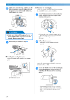
While pushing in the cap frame driver
 |
View all Brother International Entrepreneur PR-650 manuals
Add to My Manuals
Save this manual to your list of manuals |
Page 230 highlights
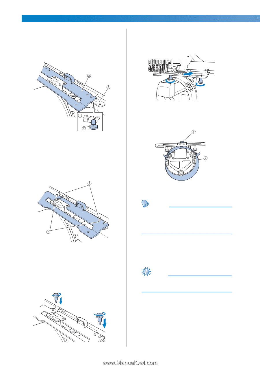
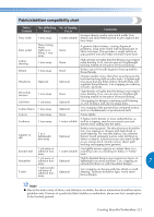
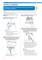
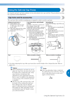
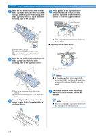
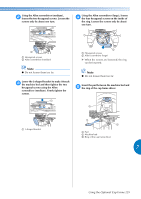
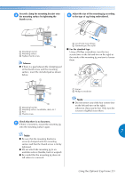
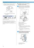
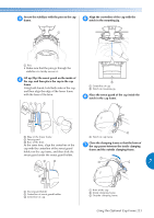
APPENDIX Insert the two thumb screws at the bottom 4 of the cap frame driver into the v-cuts in the carriage, and then place the mounting plate of the cap frame driver on top of the framemounting plate of the carriage. While pushing in the cap frame driver 7 toward the machine so that it is fully inserted, tighten the two lower thumb screws to secure the cap frame driver. 1 Notch in the carriage 2 Thumb screw of the cap frame driver 3 Mounting plate of the cap frame driver 4 Frame-mounting plate of the carriage Insert the pins on the frame-mounting plate 5 of the carriage into the holes in the mounting plate of the cap frame driver. X This completes the installation of the cap frame driver. ■ Adjusting the cap frame driver 1 L-shaped bracket 2 Ring Memo ● If the same machine is being used, the adjustment to the cap frame driver is only required the first time that the machine is used. 1 Pins on the frame-mounting plate of the carriage 2 Holes in the mounting plate of the cap frame driver Insert and tighten the two upper thumb 6 screws in outer holes of mounting plate of cap frame driver. Turn on the machine. After the carriage 1 moves to its initial position, turn off the machine. Note ● Be sure to adjust the cap frame driver with the carriage at its initial position. 228
-
 1
1 -
2
-
3
-
4
-
5
-
6
-
7
-
8
-
9
-
10
-
11
-
12
-
13
-
14
-
15
-
16
-
17
-
18
-
19
-
20
-
21
-
22
-
23
-
24
-
25
-
26
-
27
-
28
-
29
-
30
-
31
-
32
-
33
-
34
-
35
-
36
-
37
-
38
-
39
-
40
-
41
-
42
-
43
-
44
-
45
-
46
-
47
-
48
-
49
-
50
-
51
-
52
-
53
-
54
-
55
-
56
-
57
-
58
-
59
-
60
-
61
-
62
-
63
-
64
-
65
-
66
-
67
-
68
-
69
-
70
-
71
-
72
-
73
-
74
-
75
-
76
-
77
-
78
-
79
-
80
-
81
-
82
-
83
-
84
-
85
-
86
-
87
-
88
-
89
-
90
-
91
-
92
-
93
-
94
-
95
-
96
-
97
-
98
-
99
-
100
-
101
-
102
-
103
-
104
-
105
-
106
-
107
-
108
-
109
-
110
-
111
-
112
-
113
-
114
-
115
-
116
-
117
-
118
-
119
-
120
-
121
-
122
-
123
-
124
-
125
-
126
-
127
-
128
-
129
-
130
-
131
-
132
-
133
-
134
-
135
-
136
-
137
-
138
-
139
-
140
-
141
-
142
-
143
-
144
-
145
-
146
-
147
-
148
-
149
-
150
-
151
-
152
-
153
-
154
-
155
-
156
-
157
-
158
-
159
-
160
-
161
-
162
-
163
-
164
-
165
-
166
-
167
-
168
-
169
-
170
-
171
-
172
-
173
-
174
-
175
-
176
-
177
-
178
-
179
-
180
-
181
-
182
-
183
-
184
-
185
-
186
-
187
-
188
-
189
-
190
-
191
-
192
-
193
-
194
-
195
-
196
-
197
-
198
-
199
-
200
-
201
-
202
-
203
-
204
-
205
-
206
-
207
-
208
-
209
-
210
-
211
-
212
-
213
-
214
-
215
-
216
-
217
-
218
-
219
-
220
-
221
-
222
-
223
-
224
-
 225
225 -
 226
226 -
 227
227 -
 228
228 -
 229
229 -
 230
230 -
 231
231 -
 232
232 -
 233
233 -
 234
234 -
 235
235 -
236
-
237
-
238
-
239
-
240
-
241
-
242
-
243
-
244
-
245
-
246
-
247
-
248
-
249
-
250
-
251
-
252
-
253
-
254
-
255
-
256
-
257
-
258
-
259
-
260
-
261
-
262
-
263
-
264
-
265
-
266
-
267
-
268
-
269
-
270
-
271
-
272
-
273
-
274
-
275
-
276
-
277
-
278
-
279
-
280
 |
 |