Brother International Entrepreneur PR-650 Users Manual - English - Page 233
Adjust the size of the mounting jig according
 |
View all Brother International Entrepreneur PR-650 manuals
Add to My Manuals
Save this manual to your list of manuals |
Page 233 highlights
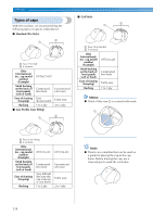
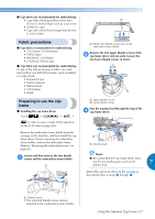
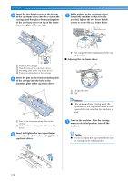
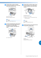
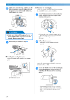
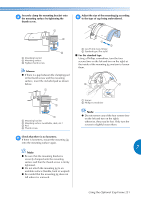
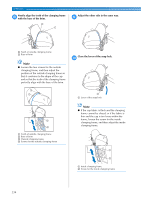
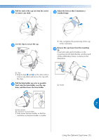
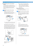
Securely clamp the mounting bracket onto 4 the mounting surface by tightening the thumb screw. Adjust the size of the mounting jig according 6 to the type of cap being embroidered. 1 Mounting bracket 2 Mounting surface 3 Tighten thumb screw Memo ● If there is a gap between the clamping pad of the thumb screw and the mounting surface, insert the included pad as shown below. 1 Low Profile (Low fitting) 2 Standard type (Pro style) ■ For the standard type Using a Phillips screwdriver, turn the four screws (two on the left and two on the right) at the inside of the mounting jig one turn to loosen them. 1 Mounting bracket 2 Mounting surface (worktable, desk, etc.) 3 Pad 4 Thumb screw Check that there is no looseness. 5 If there is looseness, mount the mounting jig onto the mounting surface again. Note ● Be sure that the mounting bracket is securely clamped onto the mounting surface and that the thumb screw is firmly tightened. ● Do not attach the mounting jig to an unstable surface (flexible, bent or warped). ● Be careful that the mounting jig does not fall when it is removed. 1 Screws 2 Phillips screwdriver Note ● Do not remove any of the four screws (two on the left and two on the right); otherwise, they may be lost. Only turn the screws to slightly loosen them. 7 Using the Optional Cap Frame 231
-
 1
1 -
2
-
3
-
4
-
5
-
6
-
7
-
8
-
9
-
10
-
11
-
12
-
13
-
14
-
15
-
16
-
17
-
18
-
19
-
20
-
21
-
22
-
23
-
24
-
25
-
26
-
27
-
28
-
29
-
30
-
31
-
32
-
33
-
34
-
35
-
36
-
37
-
38
-
39
-
40
-
41
-
42
-
43
-
44
-
45
-
46
-
47
-
48
-
49
-
50
-
51
-
52
-
53
-
54
-
55
-
56
-
57
-
58
-
59
-
60
-
61
-
62
-
63
-
64
-
65
-
66
-
67
-
68
-
69
-
70
-
71
-
72
-
73
-
74
-
75
-
76
-
77
-
78
-
79
-
80
-
81
-
82
-
83
-
84
-
85
-
86
-
87
-
88
-
89
-
90
-
91
-
92
-
93
-
94
-
95
-
96
-
97
-
98
-
99
-
100
-
101
-
102
-
103
-
104
-
105
-
106
-
107
-
108
-
109
-
110
-
111
-
112
-
113
-
114
-
115
-
116
-
117
-
118
-
119
-
120
-
121
-
122
-
123
-
124
-
125
-
126
-
127
-
128
-
129
-
130
-
131
-
132
-
133
-
134
-
135
-
136
-
137
-
138
-
139
-
140
-
141
-
142
-
143
-
144
-
145
-
146
-
147
-
148
-
149
-
150
-
151
-
152
-
153
-
154
-
155
-
156
-
157
-
158
-
159
-
160
-
161
-
162
-
163
-
164
-
165
-
166
-
167
-
168
-
169
-
170
-
171
-
172
-
173
-
174
-
175
-
176
-
177
-
178
-
179
-
180
-
181
-
182
-
183
-
184
-
185
-
186
-
187
-
188
-
189
-
190
-
191
-
192
-
193
-
194
-
195
-
196
-
197
-
198
-
199
-
200
-
201
-
202
-
203
-
204
-
205
-
206
-
207
-
208
-
209
-
210
-
211
-
212
-
213
-
214
-
215
-
216
-
217
-
218
-
219
-
220
-
221
-
222
-
223
-
224
-
225
-
226
-
227
-
 228
228 -
 229
229 -
 230
230 -
 231
231 -
 232
232 -
 233
233 -
 234
234 -
 235
235 -
 236
236 -
 237
237 -
 238
238 -
239
-
240
-
241
-
242
-
243
-
244
-
245
-
246
-
247
-
248
-
249
-
250
-
251
-
252
-
253
-
254
-
255
-
256
-
257
-
258
-
259
-
260
-
261
-
262
-
263
-
264
-
265
-
266
-
267
-
268
-
269
-
270
-
271
-
272
-
273
-
274
-
275
-
276
-
277
-
278
-
279
-
280
 |
 |
