Brother International S-7200B Service Manual - Page 37
Adjusting the needle bar height, 6-9. Adjusting the needle and feed mechanism timing
 |
View all Brother International S-7200B manuals
Add to My Manuals
Save this manual to your list of manuals |
Page 37 highlights
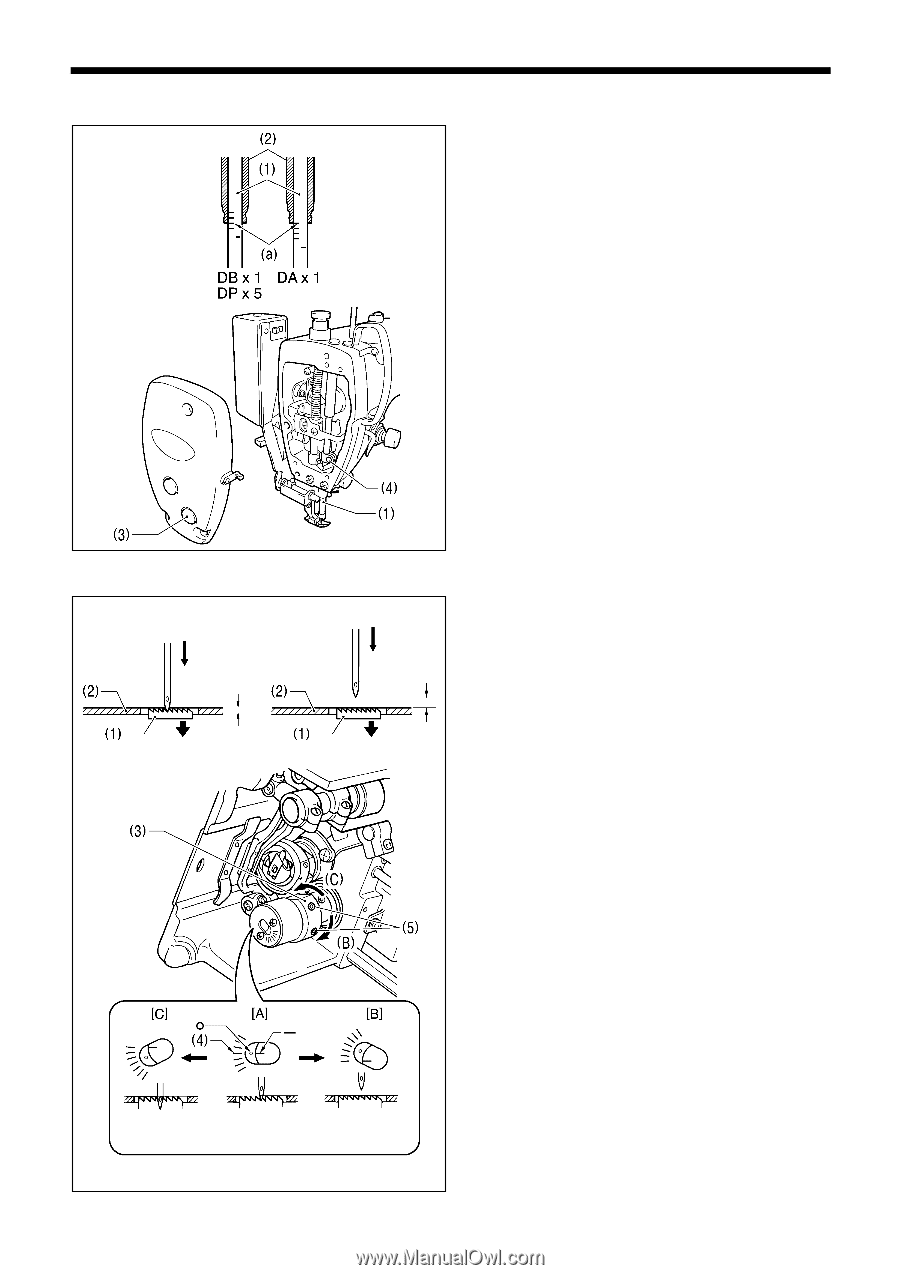
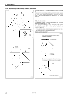
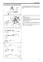
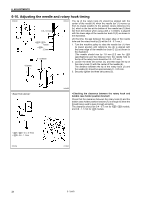
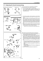
6. ADJUSTMENTS 6-8. Adjusting the needle bar height 2286M Reference line (a), which is the second line from the bottom of the needle bar (1)(fourth line from the bottom when using a DA x 1 needle) should be aligned with the lower edge of the needle bar bush D (2) as shown in the illustration when the needle bar (1) is at its lowest position. 1. Turn the machine pulley to set the needle bar (1) to its lowest position. 2. Remove the oil cap (3). 3. Loosen the screw (4) and then move the needle bar (1) up or down to adjust its position. 4. Securely tighten the screw (4). 5. Replace the oil cap (3). 3698M 6-9. Adjusting the needle and feed mechanism timing Approx. 1mm Needle timing is advanced (Standard) 2288M Approx. 3mm Needle timing is retarded 3699M The standard position for point of the needle is as described below when the feed dog (1) is lowered from its highest position until it is aligned with the top of the needle plate (2). (At this time, the "-" mark on the lower shaft will be aligned with the center of the scale (4) ("O" mark) on the vertical cam (3).) The top of the feed dog (1) and the top of the needle plate (2) should be aligned, and the point of the needle should be approximately 1 mm below the needle plate (2). The top of the feed dog (1) and the top of the needle plate (2) should be aligned, and there should be a clearance of approximately 3 mm between the point of the needle and the needle plate (2). 1. Tilt back the machine head. 2. Loosen the two set screws (5), and then turn the vertical cam (3) sligtly to adjust the timing. (Use the "-" mark on the lower shaft and the alignment position on the scale (4) of the vertical cam (3) as a guide.) ・ To set to the standard position, align the "-" mark on the lower shaft with the center of the scale (4) ("O" mark) on the vertical cam (3). ([A] in the illustration) ・ To prevent material slippage from occurring, retard the needle timing. (Turn the vertical cam (3) in the direction of (B). Refer to [B] in the illustration.) ・ To improve thread tightening, advance the needle timing. (Turn the vertical cam (3) in the direction of (C). Refer to [C] in the illustration.) NOTE: Do not turn the vertical cam (3) too far in the direction of (C), otherwise it could cause the needle to break. 3. After adjustment is completed, securely tighten the two screws (5). S-7200B 30
-
 1
1 -
2
-
3
-
4
-
5
-
6
-
7
-
8
-
9
-
10
-
11
-
12
-
13
-
14
-
15
-
16
-
17
-
18
-
19
-
20
-
21
-
22
-
23
-
24
-
25
-
26
-
27
-
28
-
29
-
30
-
31
-
 32
32 -
 33
33 -
 34
34 -
 35
35 -
 36
36 -
 37
37 -
 38
38 -
 39
39 -
 40
40 -
 41
41 -
 42
42 -
43
-
44
-
45
-
46
-
47
-
48
-
49
-
50
-
51
-
52
-
53
-
54
-
55
-
56
-
57
-
58
-
59
-
60
-
61
-
62
-
63
-
64
-
65
-
66
-
67
-
68
-
69
-
70
-
71
-
72
-
73
-
74
-
75
-
76
-
77
-
78
-
79
-
80
-
81
-
82
-
83
-
84
 |
 |