Brother International S-7200B Service Manual - Page 42
Brother International S-7200B Manual
 |
View all Brother International S-7200B manuals
Add to My Manuals
Save this manual to your list of manuals |
Page 42 highlights
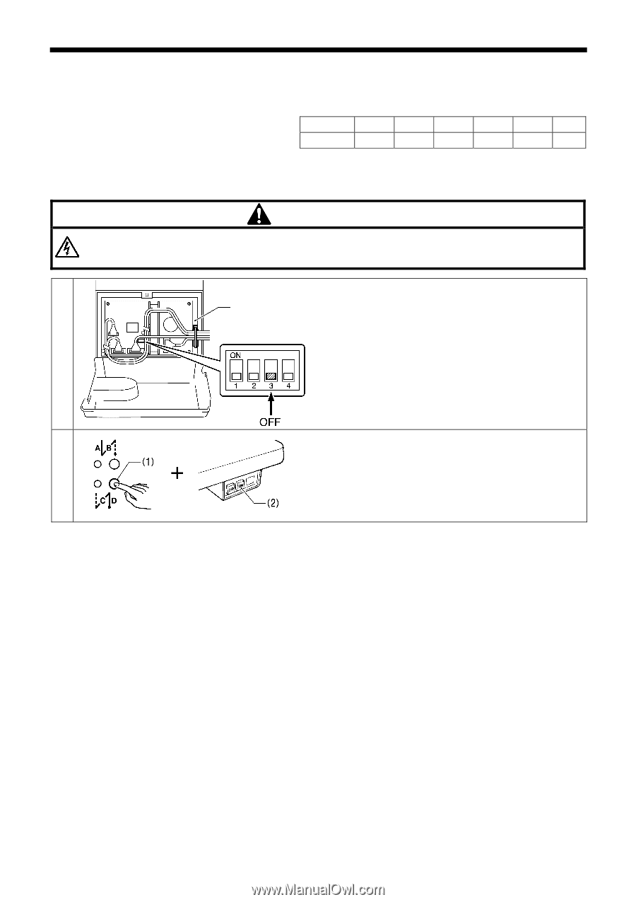
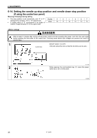
6. ADJUSTMENTS 6-14. Setting the needle up stop position and needle down stop position (If using the control box panel) Meaning of displays during setting • The stop position is set numerically, and "A" to "F" Display A b c d E F represent the numbers "10" to "15" respectively. • A setting value of "8" corresponds to an angle of Value 10 11 12 13 14 15 rotation of approximately 8° for the upper shaft. DANGER Wait at least 5 minutes after turning off the power switch and disconnecting the power cord from the wall outlet before opening the face plate of the control box. Touching areas where high voltages are present can result in severe injury. 1 Set DIP switch -3 to OFF. Control box (This will cancel the lock so that the functions can be set.) 3143M 2 While pressing the end backtack key (1), press the power switch (2) to turn on the power. 0706B 35 S-7200B
-
 1
1 -
2
-
3
-
4
-
5
-
6
-
7
-
8
-
9
-
10
-
11
-
12
-
13
-
14
-
15
-
16
-
17
-
18
-
19
-
20
-
21
-
22
-
23
-
24
-
25
-
26
-
27
-
28
-
29
-
30
-
31
-
32
-
33
-
34
-
35
-
36
-
 37
37 -
 38
38 -
 39
39 -
 40
40 -
 41
41 -
 42
42 -
 43
43 -
 44
44 -
 45
45 -
 46
46 -
 47
47 -
48
-
49
-
50
-
51
-
52
-
53
-
54
-
55
-
56
-
57
-
58
-
59
-
60
-
61
-
62
-
63
-
64
-
65
-
66
-
67
-
68
-
69
-
70
-
71
-
72
-
73
-
74
-
75
-
76
-
77
-
78
-
79
-
80
-
81
-
82
-
83
-
84
 |
 |