Brother International S-7200B Service Manual - Page 59
Control circuit board, <Name and function of each part>
 |
View all Brother International S-7200B manuals
Add to My Manuals
Save this manual to your list of manuals |
Page 59 highlights
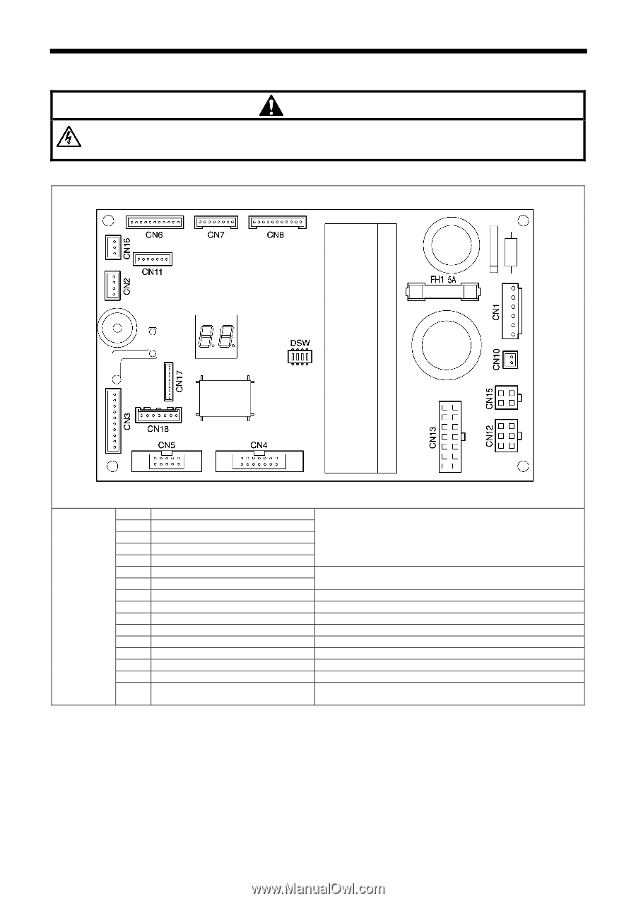
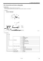
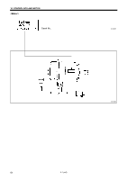
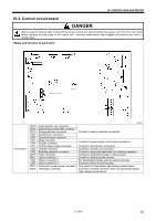
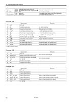
10. CONTROL BOX AND MOTOR 10-3. Control circuit board DANGER Wait at least 5 minutes after turning off the power switch and disconnecting the power cord from the wall outlet before opening the face plate of the control box. Touching areas where high voltages are present can result in severe injury. Connectors CN18 CN12 CN13 CN4 CN5 CN7 CN8 CN1 CN2 CN3 CN15 CN11 CN6 CN9 CN10 CN16 Head detector unit connector Solenoid-type presser lifter connector Sewing machine connector Synchronizer connector Operation panel connector Relay connector Coupler connector Control power supply connector Treadle connector Standing operation connector Puller connector Option connector 1 Option connector 2 Option connector 3 Cooling fan power supply connector Thermistor connector Connect to sewing machine connectors. 0657B Connect to power supply circuit board connectors. Connect to transformer connectors. Connect to treadle unit connector. Connect to plug (sold separately) for standing operation Connect to solenoid for puller or other device. Connect to sewing speed actuator. For input/output signals used by external devices Connect to stitch counter actuator. Only used for three-phase high-voltage specifications. Connect to shorted connector when not using three-phase high-voltage specifications. S-7200B 52
-
 1
1 -
2
-
3
-
4
-
5
-
6
-
7
-
8
-
9
-
10
-
11
-
12
-
13
-
14
-
15
-
16
-
17
-
18
-
19
-
20
-
21
-
22
-
23
-
24
-
25
-
26
-
27
-
28
-
29
-
30
-
31
-
32
-
33
-
34
-
35
-
36
-
37
-
38
-
39
-
40
-
41
-
42
-
43
-
44
-
45
-
46
-
47
-
48
-
49
-
50
-
51
-
52
-
53
-
 54
54 -
 55
55 -
 56
56 -
 57
57 -
 58
58 -
 59
59 -
 60
60 -
 61
61 -
 62
62 -
 63
63 -
 64
64 -
65
-
66
-
67
-
68
-
69
-
70
-
71
-
72
-
73
-
74
-
75
-
76
-
77
-
78
-
79
-
80
-
81
-
82
-
83
-
84
 |
 |