Brother International S-7200B Service Manual - Page 61
Checking the motor and power supply, <Motor>, <Power switch>
 |
View all Brother International S-7200B manuals
Add to My Manuals
Save this manual to your list of manuals |
Page 61 highlights
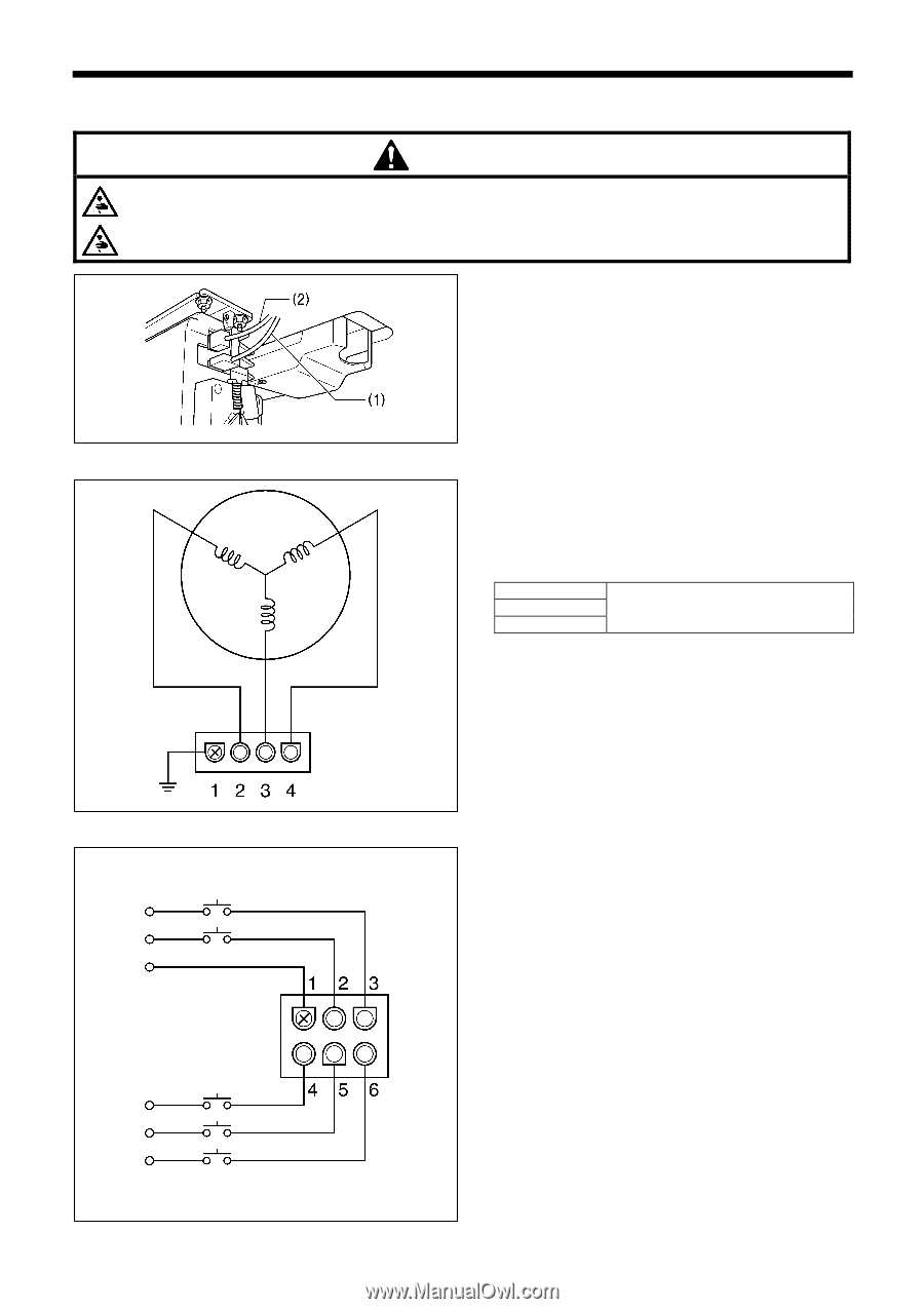
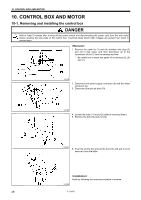
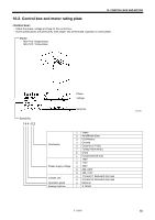
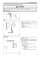
10. CONTROL BOX AND MOTOR 10-4. Checking the motor and power supply CAUTION Turn off the power switch and disconnect the power cord from the wall outlet before carrying out these operations. The machine may operate if the treadle is depressed by mistake, which could result in injury. If the power switch needs to be left on when carrying out some adjustment, be extremely careful to observe all safety precautions. U phase W phase V phase 2329M 1. Disconnect the motor connector 4P (1) from the control box. 2. Measure the resistance of the motor connector (1) using an ohmmeter in the x 1 range. If the value is as shown in the table below, the connector is normal. Between 2-3 Between 3-4 Between 4-2 Approx. 1.6Ω Ground wire 1883M 1. Disconnect the power supply connector 6P (2) from the control box. 2. Turn on the power switch. 3. Measure the voltage at the power supply connector (2) using the AC voltage range of a multimeter, and check that the voltage is within the allowable range for the specified voltage rating. 100 V type (100-120 V) Measure the AC voltage between terminals 2-3. 200 V type (200-240 V) [A] For three-phase Measure the AC voltage between terminals 4-5, 5-6 and 6-4. [B] For single-phase Measure the AC voltage between terminals 4-6. 1884M S-7200B 54
-
 1
1 -
2
-
3
-
4
-
5
-
6
-
7
-
8
-
9
-
10
-
11
-
12
-
13
-
14
-
15
-
16
-
17
-
18
-
19
-
20
-
21
-
22
-
23
-
24
-
25
-
26
-
27
-
28
-
29
-
30
-
31
-
32
-
33
-
34
-
35
-
36
-
37
-
38
-
39
-
40
-
41
-
42
-
43
-
44
-
45
-
46
-
47
-
48
-
49
-
50
-
51
-
52
-
53
-
54
-
55
-
 56
56 -
 57
57 -
 58
58 -
 59
59 -
 60
60 -
 61
61 -
 62
62 -
 63
63 -
 64
64 -
 65
65 -
 66
66 -
67
-
68
-
69
-
70
-
71
-
72
-
73
-
74
-
75
-
76
-
77
-
78
-
79
-
80
-
81
-
82
-
83
-
84
 |
 |