Brother International S-7200B Service Manual - Page 7

Contents

Page 7 highlights

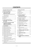
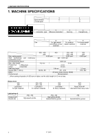
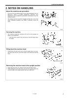
CONTENTS 1. MACHINE SPECIFICATIONS 1 2. NOTES ON HANDLING 2 3. FUNCTION SETTINGS (OPERATION PANEL 3 3-1. Maximum sewing speed and start backtack sewing speed setting methods 3 3-2. Using the LOCK key 4 3-3. Setting the DIP switches 4 3-4. Setting functions 5 3-5. Function List 6 3-6. Clearing saved data (Initialization 21 4. INITIALIZING THE CONTROL BOX PANEL 22 5. ADJUSTING THE ROTARY HOOK LUBRICATION AMOUNT (-[]0[], []3[] specifications 23 6. ADJUSTMENTS 24 6-1. Adjusting the actuator position 24 6-2. Adjusting the safety switch position 25 6-3. Adjusting the thread take-up spring 26 6-4. Adjusting arm thread guide R 27 6-5. Adjusting the presser foot height 27 6-6. Adjusting of the feed dog height 28 6-7. Adjusting the feed dog angle 29 6-8. Adjusting the needle bar height 30 6-9. Adjusting the needle and feed mechanism timing.... 30 6-10. Adjusting the needle and rotary hook timing .......... 31 6-11. Adjusting the thread trimming timing 32 6-12. Adjusting the thread take-up amount (-[][]3 specifications 33 6-13. Adjusting the needle up stop position (When using the operation panel 34 6-14. Setting the needle up stop position and needle down stop position (If using the control box panel 35 6-15. Adjusting the treadle 37 6-16. Adjusting the presser foot floating amount (minute lifting amount 37 7. REPLACING PARTS 38 7-1. Fixed knife 38 7-2. Movable knife 38 7-3. Motor and timing belt 39 7-4. Rotary hook RP 42 7-5. Feed bar shaft, Lifting feed shaft 43 8. APPLYING GREASE (-[]3[], []5[] specifications 44 8-1. When using the operation panel 44 8-2. When using the control box panel 46 9. CONTROL SYSTEM 48 10. CONTROL BOX AND MOTOR...........49 10-1. Removing and installing the control box 49 10-2. Control box and motor rating plate 50 10-3. Control circuit board 52 10-4. Checking the motor and power supply 54 10-5. Checking the solenoids 55 11. TREADLE UNIT ASSEMBLY 56 11-1. Types 56 11-2. Standard setting values 57 11-3. Setting method for standard depression strokes 58 12. STANDING OPERATION PEDAL ......62 12-1. Installing the foot plug 62 12-2. Connectors 63 13. TROUBLESHOOTING 64 13-1. Sewing 64 13-2. Error code displays 69 14. SEGMENT DISPLAY DEFINITION TABLE 74 S-7200B

  • 1
  • 2
  • 3
  • 4
  • 5
  • 6
  • 7
  • 8
  • 9
  • 10
  • 11
  • 12
  • 13
  • 14
  • 15
  • 16
  • 17
  • 18
  • 19
  • 20
  • 21
  • 22
  • 23
  • 24
  • 25
  • 26
  • 27
  • 28
  • 29
  • 30
  • 31
  • 32
  • 33
  • 34
  • 35
  • 36
  • 37
  • 38
  • 39
  • 40
  • 41
  • 42
  • 43
  • 44
  • 45
  • 46
  • 47
  • 48
  • 49
  • 50
  • 51
  • 52
  • 53
  • 54
  • 55
  • 56
  • 57
  • 58
  • 59
  • 60
  • 61
  • 62
  • 63
  • 64
  • 65
  • 66
  • 67
  • 68
  • 69
  • 70
  • 71
  • 72
  • 73
  • 74
  • 75
  • 76
  • 77
  • 78
  • 79
  • 80
  • 81
  • 82
  • 83
  • 84

S-7200B
CONTENTS
1. MACHINE SPECIFICATIONS
...............
1
2. NOTES ON HANDLING
........................
2
3. FUNCTION SETTINGS
(OPERATION PANEL)
.........................
3
3-1.
Maximum sewing speed and start backtack sewing
speed setting methods
..........................................
3
3-2.
Using the LOCK key
................................................
4
3-3.
Setting the DIP switches
..........................................
4
3-4.
Setting functions
......................................................
5
3-5.
Function List
............................................................
6
3-6.
Clearing saved data (Initialization)
...........................
21
4. INITIALIZING THE CONTROL
BOX PANEL
.........................................
22
5. ADJUSTING THE ROTARY HOOK
LUBRICATION AMOUNT
(-[]0[], []3[] specifications)
..................
23
6. ADJUSTMENTS
...................................
24
6-1.
Adjusting the actuator position
.................................
24
6-2.
Adjusting the safety switch position
..........................
25
6-3.
Adjusting the thread take-up spring
.........................
26
6-4.
Adjusting arm thread guide R
...................................
27
6-5.
Adjusting the presser foot height
..............................
27
6-6.
Adjusting of the feed dog height
...............................
28
6-7.
Adjusting the feed dog angle
....................................
29
6-8.
Adjusting the needle bar height
................................
30
6-9.
Adjusting the needle and feed mechanism timing
....
30
6-10.
Adjusting the needle and rotary hook timing
..........
31
6-11.
Adjusting the thread trimming timing
......................
32
6-12.
Adjusting the thread take-up amount
(-[][]3 specifications)
.............................................
33
6-13.
Adjusting the needle up stop position
(When using the operation panel)
..........................
34
6-14.
Setting the needle up stop position and needle down
stop position (
If using the control box panel)
.............
35
6-15.
Adjusting the treadle
..............................................
37
6-16.
Adjusting the presser foot floating amount (minute
lifting amount)
........................................................
37
7. REPLACING PARTS
............................
38
7-1.
Fixed knife
................................................................
38
7-2.
Movable knife
...........................................................
38
7-3.
Motor and timing belt
................................................
39
7-4.
Rotary hook RP
........................................................
42
7-5.
Feed bar shaft, Lifting feed shaft
..............................
43
8. APPLYING GREASE
(-[]3[], []5[] specifications)
..................
44
8-1.
When using the operation panel
...............................
44
8-2.
When using the control box panel
............................
46
9. CONTROL SYSTEM
.............................
48
10. CONTROL BOX AND MOTOR
...........
49
10-1.
Removing and installing the control box
................
49
10-2.
Control box and motor rating plate
.........................
50
10-3.
Control circuit board
...............................................
52
10-4.
Checking the motor and power supply
...................
54
10-5.
Checking the solenoids
..........................................
55
11. TREADLE UNIT ASSEMBLY
.............
56
11-1.
Types
.....................................................................
56
11-2.
Standard setting values
.........................................
57
11-3.
Setting method for standard depression
strokes
...................................................................
58
12. STANDING OPERATION PEDAL
......
62
12-1.
Installing the foot plug
............................................
62
12-2.
Connectors
............................................................
63
13. TROUBLESHOOTING
........................
64
13-1.
Sewing
...................................................................
64
13-2.
Error code displays
................................................
69
14. SEGMENT DISPLAY DEFINITION
TABLE
................................................
74