Canon PC980 Service Manual - Page 100
Turning On and Off the AC Bias, Controlling the DC/AC Bias to a Specific Voltage/Current, Reference
 |
UPC - 030275182323
View all Canon PC980 manuals
Add to My Manuals
Save this manual to your list of manuals |
Page 100 highlights
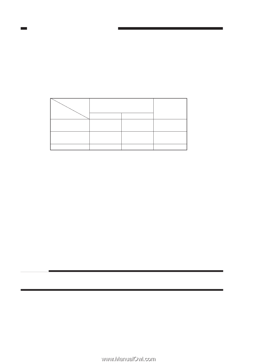
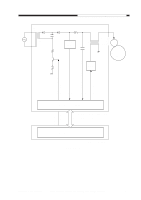
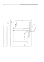
CHAPTER 4 IMAGE FORMATION SYSTEM 2. Operations a. Turning On and Off the DC Bias The DC bias applied to the primary charging roller is turned on or off by the serial communication signal and the primary charging bias ON signal (PR_DC_ON) from the DC controller PCB. When the Copy Start key is pressed, the DC bias ON signal (serial) and the primary charging bias ON signal (PR_DC_ON) are sent. The microprocessor (Q900) on the composite power supply PCB generates the DC bias control signal (PDC_PWM) based on the combination of the serial signal and the PR_DC_ON signal, applying a DC bias to the primary charging roller. DC bias ON (image area) DC bias ON (non-image area) DC bias OFF DC bias ON signal (8-bit signal communication) bit0 bit1 1 - 1 0 0 0 PR_DC_ON (J103-4) 0 1 1 Table 4-102 Relationship between DC Bias Output and Signal b. Turning On and Off the AC Bias The AC bias applied to the primary charging roller is turned on and off by the serial communi- cation signal from the DC controller PCB. When the AC bias ON signal arrives from the DC controller PCB, the microprocessor (Q900) on the composite power supply PCB generates the AC bias output signal (PAC_OUT), thereby applying an AC bias to the primary charging roller. c. Controlling the DC/AC Bias to a Specific Voltage/Current The DC bias and the AC bias applied to the primary charging roller are controlled by the microprocessor (Q900) on the composite power supply PCB so that they remain a specific level. When a DC/AC bias is generated, the microprocessor (Q900) on the composite power supply PCB detects the DC voltage monitor signal (PDC_S) and the AC component current monitor signal (PAC_S), compares their levels against the reference levels, and varies the DC bias control signal (PDC_PWM) and the AC bias output signal (PAC_OUT) according to the differences so as to ensure that they remain specific levels. Reference: The DC bias control signal varies its pulse duty ratio while the AC bias output signal varies its amplitude to change the level of the DC/AC bias. 4-6 COPYRIGHT © 1999 CANON INC. CANON PC800s/900s REV.0 AUG. 1999 PRINTED IN JAPAN (IMPRIME AU JAPON)
-
 1
1 -
2
-
3
-
4
-
5
-
6
-
7
-
8
-
9
-
10
-
11
-
12
-
13
-
14
-
15
-
16
-
17
-
18
-
19
-
20
-
21
-
22
-
23
-
24
-
25
-
26
-
27
-
28
-
29
-
30
-
31
-
32
-
33
-
34
-
35
-
36
-
37
-
38
-
39
-
40
-
41
-
42
-
43
-
44
-
45
-
46
-
47
-
48
-
49
-
50
-
51
-
52
-
53
-
54
-
55
-
56
-
57
-
58
-
59
-
60
-
61
-
62
-
63
-
64
-
65
-
66
-
67
-
68
-
69
-
70
-
71
-
72
-
73
-
74
-
75
-
76
-
77
-
78
-
79
-
80
-
81
-
82
-
83
-
84
-
85
-
86
-
87
-
88
-
89
-
90
-
91
-
92
-
93
-
94
-
 95
95 -
 96
96 -
 97
97 -
 98
98 -
 99
99 -
 100
100 -
 101
101 -
 102
102 -
 103
103 -
 104
104 -
 105
105 -
106
-
107
-
108
-
109
-
110
-
111
-
112
-
113
-
114
-
115
-
116
-
117
-
118
-
119
-
120
-
121
-
122
-
123
-
124
-
125
-
126
-
127
-
128
-
129
-
130
-
131
-
132
-
133
-
134
-
135
-
136
-
137
-
138
-
139
-
140
-
141
-
142
-
143
-
144
-
145
-
146
-
147
-
148
-
149
-
150
-
151
-
152
-
153
-
154
-
155
-
156
-
157
-
158
-
159
-
160
-
161
-
162
-
163
-
164
-
165
-
166
-
167
-
168
-
169
-
170
-
171
-
172
-
173
-
174
-
175
-
176
-
177
-
178
-
179
-
180
-
181
-
182
-
183
-
184
-
185
-
186
-
187
-
188
-
189
-
190
-
191
-
192
-
193
-
194
-
195
-
196
-
197
-
198
-
199
-
200
-
201
-
202
-
203
-
204
-
205
-
206
-
207
-
208
-
209
-
210
-
211
-
212
-
213
-
214
-
215
-
216
-
217
-
218
-
219
-
220
-
221
-
222
-
223
-
224
-
225
-
226
-
227
-
228
-
229
-
230
-
231
-
232
-
233
-
234
-
235
-
236
-
237
-
238
-
239
-
240
-
241
-
242
-
243
-
244
-
245
-
246
-
247
-
248
-
249
-
250
-
251
-
252
-
253
-
254
-
255
-
256
-
257
-
258
-
259
-
260
-
261
-
262
-
263
-
264
-
265
-
266
-
267
-
268
-
269
-
270
-
271
-
272
-
273
-
274
-
275
-
276
-
277
-
278
-
279
-
280
-
281
-
282
-
283
-
284
-
285
-
286
-
287
-
288
-
289
-
290
-
291
-
292
-
293
-
294
-
295
-
296
-
297
-
298
-
299
-
300
-
301
-
302
-
303
-
304
-
305
-
306
-
307
-
308
-
309
-
310
-
311
-
312
-
313
-
314
-
315
-
316
-
317
-
318
-
319
-
320
-
321
-
322
-
323
-
324
-
325
-
326
-
327
-
328
-
329
-
330
-
331
-
332
-
333
-
334
-
335
-
336
-
337
-
338
-
339
-
340
-
341
-
342
-
343
-
344
-
345
-
346
-
347
-
348
-
349
-
350
-
351
-
352
-
353
-
354
-
355
-
356
-
357
-
358
-
359
-
360
-
361
-
362
-
363
-
364
-
365
-
366
-
367
-
368
-
369
-
370
-
371
-
372
-
373
-
374
-
375
-
376
-
377
-
378
-
379
-
380
-
381
-
382
-
383
-
384
-
385
-
386
-
387
-
388
-
389
-
390
-
391
-
392
-
393
 |
 |