Canon PC980 Service Manual - Page 143
Pickup Assembly, Removing the Pickup Roller
 |
UPC - 030275182323
View all Canon PC980 manuals
Add to My Manuals
Save this manual to your list of manuals |
Page 143 highlights
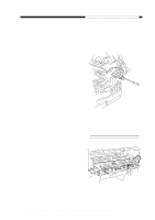
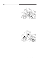
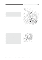
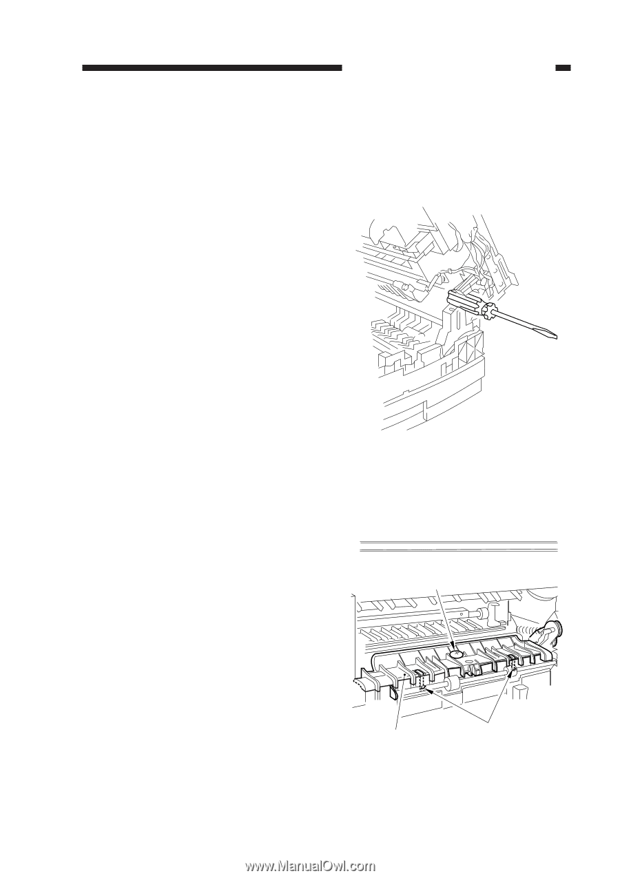
CHAPTER 5 PICK-UP/FEEDING SYSTEM A. Pickup Assembly 1. Removing the Pickup Roller 1) Pull out the cassette. 2) Remove the front lower cover. (See Chapter 7.III.A.2."Removing the Front Lower Cover.") 3) Open the machines' top unit farther, and hold it in place with the handle of a screwdriver (about 30 mm in diameter). 4) Remove the screw [1], and free the two claws [2]; then, detach the feeding assembly cover [3]. Figure 5-201 [1] [2] [3] Figure 5-202 COPYRIGHT © 1999 CANON INC. CANON PC800s/900s REV.0 AUG. 1999 PRINTED IN JAPAN (IMPRIME AU JAPON) 5-19
-
 1
1 -
2
-
3
-
4
-
5
-
6
-
7
-
8
-
9
-
10
-
11
-
12
-
13
-
14
-
15
-
16
-
17
-
18
-
19
-
20
-
21
-
22
-
23
-
24
-
25
-
26
-
27
-
28
-
29
-
30
-
31
-
32
-
33
-
34
-
35
-
36
-
37
-
38
-
39
-
40
-
41
-
42
-
43
-
44
-
45
-
46
-
47
-
48
-
49
-
50
-
51
-
52
-
53
-
54
-
55
-
56
-
57
-
58
-
59
-
60
-
61
-
62
-
63
-
64
-
65
-
66
-
67
-
68
-
69
-
70
-
71
-
72
-
73
-
74
-
75
-
76
-
77
-
78
-
79
-
80
-
81
-
82
-
83
-
84
-
85
-
86
-
87
-
88
-
89
-
90
-
91
-
92
-
93
-
94
-
95
-
96
-
97
-
98
-
99
-
100
-
101
-
102
-
103
-
104
-
105
-
106
-
107
-
108
-
109
-
110
-
111
-
112
-
113
-
114
-
115
-
116
-
117
-
118
-
119
-
120
-
121
-
122
-
123
-
124
-
125
-
126
-
127
-
128
-
129
-
130
-
131
-
132
-
133
-
134
-
135
-
136
-
137
-
 138
138 -
 139
139 -
 140
140 -
 141
141 -
 142
142 -
 143
143 -
 144
144 -
 145
145 -
 146
146 -
 147
147 -
 148
148 -
149
-
150
-
151
-
152
-
153
-
154
-
155
-
156
-
157
-
158
-
159
-
160
-
161
-
162
-
163
-
164
-
165
-
166
-
167
-
168
-
169
-
170
-
171
-
172
-
173
-
174
-
175
-
176
-
177
-
178
-
179
-
180
-
181
-
182
-
183
-
184
-
185
-
186
-
187
-
188
-
189
-
190
-
191
-
192
-
193
-
194
-
195
-
196
-
197
-
198
-
199
-
200
-
201
-
202
-
203
-
204
-
205
-
206
-
207
-
208
-
209
-
210
-
211
-
212
-
213
-
214
-
215
-
216
-
217
-
218
-
219
-
220
-
221
-
222
-
223
-
224
-
225
-
226
-
227
-
228
-
229
-
230
-
231
-
232
-
233
-
234
-
235
-
236
-
237
-
238
-
239
-
240
-
241
-
242
-
243
-
244
-
245
-
246
-
247
-
248
-
249
-
250
-
251
-
252
-
253
-
254
-
255
-
256
-
257
-
258
-
259
-
260
-
261
-
262
-
263
-
264
-
265
-
266
-
267
-
268
-
269
-
270
-
271
-
272
-
273
-
274
-
275
-
276
-
277
-
278
-
279
-
280
-
281
-
282
-
283
-
284
-
285
-
286
-
287
-
288
-
289
-
290
-
291
-
292
-
293
-
294
-
295
-
296
-
297
-
298
-
299
-
300
-
301
-
302
-
303
-
304
-
305
-
306
-
307
-
308
-
309
-
310
-
311
-
312
-
313
-
314
-
315
-
316
-
317
-
318
-
319
-
320
-
321
-
322
-
323
-
324
-
325
-
326
-
327
-
328
-
329
-
330
-
331
-
332
-
333
-
334
-
335
-
336
-
337
-
338
-
339
-
340
-
341
-
342
-
343
-
344
-
345
-
346
-
347
-
348
-
349
-
350
-
351
-
352
-
353
-
354
-
355
-
356
-
357
-
358
-
359
-
360
-
361
-
362
-
363
-
364
-
365
-
366
-
367
-
368
-
369
-
370
-
371
-
372
-
373
-
374
-
375
-
376
-
377
-
378
-
379
-
380
-
381
-
382
-
383
-
384
-
385
-
386
-
387
-
388
-
389
-
390
-
391
-
392
-
393
 |
 |
CHAPTER 5
PICK-UP/FEEDING SYSTEM
COPYRIGHT
©
1999
CANON INC.
CANON
PC800s/900s REV.0 AUG. 1999 PRINTED IN JAPAN (IMPRIME AU JAPON)
5-19
Figure 5-201
Figure 5-202
[1]
[2]
[3]
A.
Pickup Assembly
1.
Removing the Pickup Roller
1)
Pull out the cassette.
2)
Remove the front lower cover.
(See Chapter 7.III.A.2.“Removing the
Front Lower Cover.”)
3)
Open the machines' top unit farther, and
hold it in place with the handle of a screw-
driver (about 30 mm in diameter).
4)
Remove the screw [1], and free the two
claws [2]; then, detach the feeding assem-
bly cover [3].