Canon PC980 Service Manual - Page 332
AC power fails to turn
 |
UPC - 030275182323
View all Canon PC980 manuals
Add to My Manuals
Save this manual to your list of manuals |
Page 332 highlights
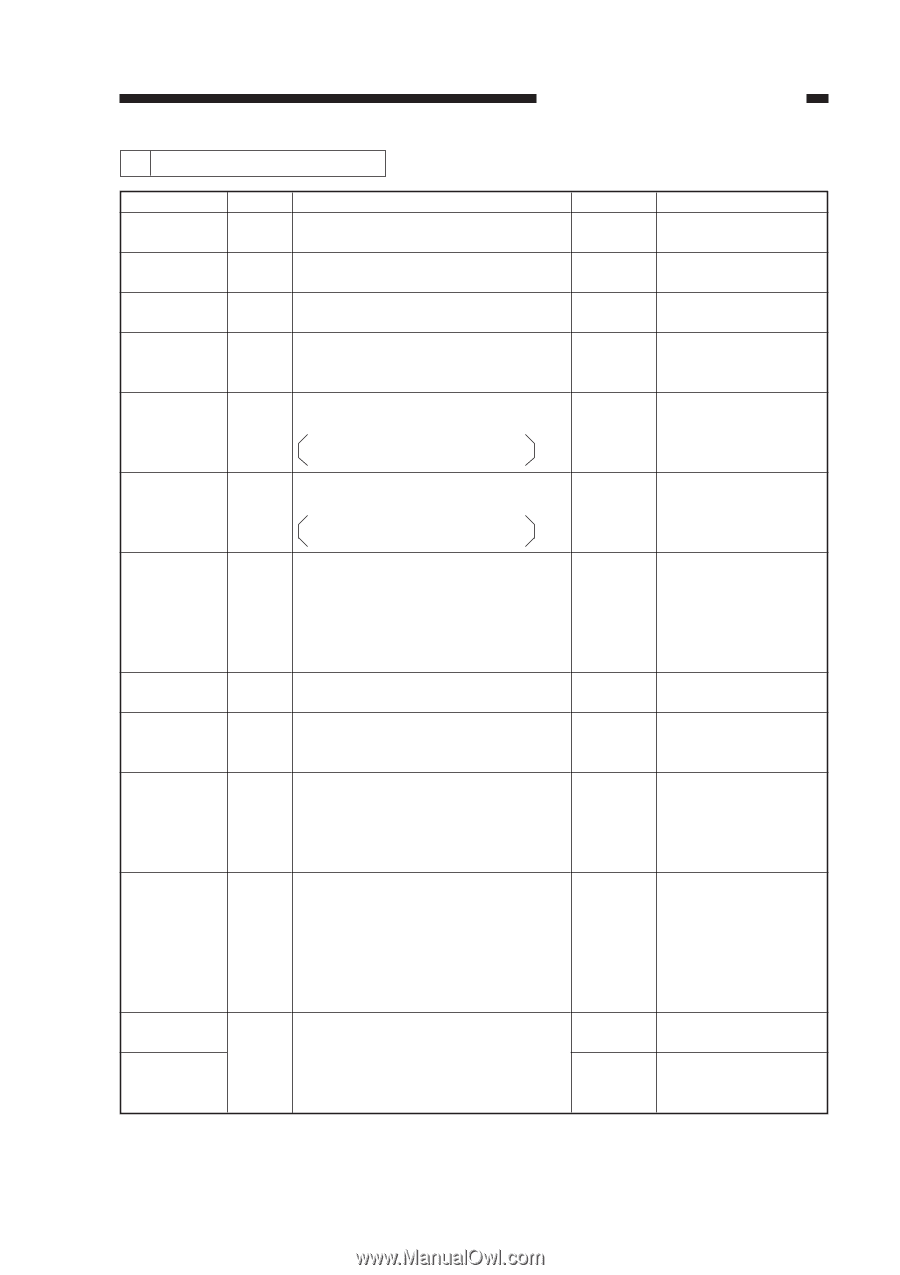
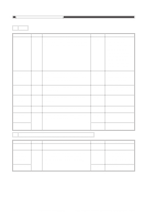
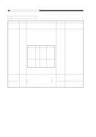
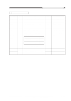
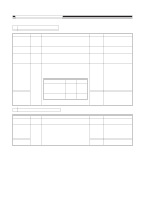
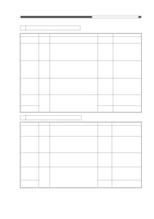
CHAPTER 11 TROUBLESHOOTING 14 AC power fails to turn on. Cause Power plug Machine top unit Power supply Fuse (FU501) Fuse (FU102) Door switch (DS1) Noise filter PCB Harness Connector connection 1 Connector connection 2 Control panel PCB Composite power supply PCB Step 1 2 3 4 5 6 7 8 9 10 11 12 Checks Is the power plug connected to the power outlet? Turn on the power switch. Is 'E0' indicated in the display? Is the machine's top unit closed firmly? Is the rated voltage present at the power outlet? Is the fuse (FU501) on the noise filter PCB blown? 120V model: 250 V, 15 A 220/240V model: 250 V, 6.3 A Is the fuse (FU102) on the composite power supply PCB blown? 120V model: 125 V, 5 A 220/240V model: 250 V, 2.5 A Remove the door switch (DS1), and connect the meter probes to F1 and F3 or F2 and F4 of the faston of the door switch. Is the resistance about 0 Ω when the actuator is pressed add about ∞ Ω when it is released? Is the rated voltage present between J501-1 and -2? Is the rated voltage present between J201-1 and J201-2? Is there electrical continuity between J111-15 on the DC controller PCB and J301-15 on the control panel PCB? Is there electrical continuity between J204-1 on the composite power supply PCB and J104-7 on the DC controller PCB? Replace the control panel PCB.Is the problem corrected? YES/NO NO YES NO NO YES Action Connect the power plug. See the descriptions under "E0." Close the machine's top unit. Inform the user that the problem is not the machine's. Remove the cause, and replace the fuse. YES Remove the cause of the problem, and replace the fuse. NO Replace the door switch (DS1). NO Replace the noise filter PCB. NO Check the connectors and the wiring if they are normal. NO Correct the electrical continuity of J111 on the DC controller PCB and J301 on the control panel PCB. NO Check the connection of J104 on the DC controller PCB and J204 on the composite power supply PCB; if normal, replace the DC controller PCB. YES End. NO Replace the composite power supply PCB. COPYRIGHT © 1999 CANON INC. CANON PC800s/900s REV.0 AUG. 1999 PRINTED IN JAPAN (IMPRIME AU JAPON) 11-67
-
 1
1 -
2
-
3
-
4
-
5
-
6
-
7
-
8
-
9
-
10
-
11
-
12
-
13
-
14
-
15
-
16
-
17
-
18
-
19
-
20
-
21
-
22
-
23
-
24
-
25
-
26
-
27
-
28
-
29
-
30
-
31
-
32
-
33
-
34
-
35
-
36
-
37
-
38
-
39
-
40
-
41
-
42
-
43
-
44
-
45
-
46
-
47
-
48
-
49
-
50
-
51
-
52
-
53
-
54
-
55
-
56
-
57
-
58
-
59
-
60
-
61
-
62
-
63
-
64
-
65
-
66
-
67
-
68
-
69
-
70
-
71
-
72
-
73
-
74
-
75
-
76
-
77
-
78
-
79
-
80
-
81
-
82
-
83
-
84
-
85
-
86
-
87
-
88
-
89
-
90
-
91
-
92
-
93
-
94
-
95
-
96
-
97
-
98
-
99
-
100
-
101
-
102
-
103
-
104
-
105
-
106
-
107
-
108
-
109
-
110
-
111
-
112
-
113
-
114
-
115
-
116
-
117
-
118
-
119
-
120
-
121
-
122
-
123
-
124
-
125
-
126
-
127
-
128
-
129
-
130
-
131
-
132
-
133
-
134
-
135
-
136
-
137
-
138
-
139
-
140
-
141
-
142
-
143
-
144
-
145
-
146
-
147
-
148
-
149
-
150
-
151
-
152
-
153
-
154
-
155
-
156
-
157
-
158
-
159
-
160
-
161
-
162
-
163
-
164
-
165
-
166
-
167
-
168
-
169
-
170
-
171
-
172
-
173
-
174
-
175
-
176
-
177
-
178
-
179
-
180
-
181
-
182
-
183
-
184
-
185
-
186
-
187
-
188
-
189
-
190
-
191
-
192
-
193
-
194
-
195
-
196
-
197
-
198
-
199
-
200
-
201
-
202
-
203
-
204
-
205
-
206
-
207
-
208
-
209
-
210
-
211
-
212
-
213
-
214
-
215
-
216
-
217
-
218
-
219
-
220
-
221
-
222
-
223
-
224
-
225
-
226
-
227
-
228
-
229
-
230
-
231
-
232
-
233
-
234
-
235
-
236
-
237
-
238
-
239
-
240
-
241
-
242
-
243
-
244
-
245
-
246
-
247
-
248
-
249
-
250
-
251
-
252
-
253
-
254
-
255
-
256
-
257
-
258
-
259
-
260
-
261
-
262
-
263
-
264
-
265
-
266
-
267
-
268
-
269
-
270
-
271
-
272
-
273
-
274
-
275
-
276
-
277
-
278
-
279
-
280
-
281
-
282
-
283
-
284
-
285
-
286
-
287
-
288
-
289
-
290
-
291
-
292
-
293
-
294
-
295
-
296
-
297
-
298
-
299
-
300
-
301
-
302
-
303
-
304
-
305
-
306
-
307
-
308
-
309
-
310
-
311
-
312
-
313
-
314
-
315
-
316
-
317
-
318
-
319
-
320
-
321
-
322
-
323
-
324
-
325
-
326
-
 327
327 -
 328
328 -
 329
329 -
 330
330 -
 331
331 -
 332
332 -
 333
333 -
 334
334 -
 335
335 -
 336
336 -
 337
337 -
338
-
339
-
340
-
341
-
342
-
343
-
344
-
345
-
346
-
347
-
348
-
349
-
350
-
351
-
352
-
353
-
354
-
355
-
356
-
357
-
358
-
359
-
360
-
361
-
362
-
363
-
364
-
365
-
366
-
367
-
368
-
369
-
370
-
371
-
372
-
373
-
374
-
375
-
376
-
377
-
378
-
379
-
380
-
381
-
382
-
383
-
384
-
385
-
386
-
387
-
388
-
389
-
390
-
391
-
392
-
393
 |
 |