Canon PIXMA MP530 Easy Setup Instructions
Canon PIXMA MP530 Manual
 |
View all Canon PIXMA MP530 manuals
Add to My Manuals
Save this manual to your list of manuals |
Canon PIXMA MP530 manual content summary:
- Canon PIXMA MP530 | Easy Setup Instructions - Page 1
and the Scanning Unit (Printer Cover). Click The pattern is printed. And Print Head is aligned automatically. Cassette 2 Load the stack of paper into the Cassette with the print side face down. Pinch the Paper Guide and align it to the stack. Paper Guide If the message appears - Canon PIXMA MP530 | Easy Setup Instructions - Page 2
the machine ON. The software will begin identifying the printer port being used. IMPORTANT If you cannot proceed to the next procedure after three minuets, refer to "Troubleshooting" instructions in the User's Guide. Macintosh® MP Drivers Installation Macintosh • A printer cable is not included
-
 1
1 -
 2
2
 |
 |
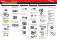
Start Here
Easy Setup Instructions
Unpack the machine
Please confirm bundled thing by the illustration printed on the flapped lid of the packing box.
QT5-0214-V01
Hardware setup and Print Head
alignment is complete.
If you are connecting the machine to a computer for
use, see the back side of this sheet for instructions on
installing the software.
For fax users
To send a fax, you need to set the
telephone line type setting properly on
the machine.
You have a dedicated telephone line for
fax use only:
→
FAX ONLY MODE
You receive mainly voice calls and
sometimes faxes, and you want to receive
faxes manually:
→
MANUAL MODE
You want to receive voice messages on
your answering machine, and receive
faxes automatically:
→
ANS.MACHINE MODE
You want to switch faxes and voice calls
automatically:
→
FAX/TEL AUTO SW
You have subscribed to a Distinctive Ring
Pattern Detection (DRPD) service with your
telephone company:
→
DRPD
For details about the receive mode
setting, refer to “Receiving Faxes” in the
User’s Guide
.
If you are unsure of your telephone line
type, contact your telephone company.
Cassette Loading
You can load paper in both the Auto Sheet Feeder
and Cassette.
1
Pull out the Cassette from the bottom
of the machine.
Cassette
2
Load the stack of paper into the
Cassette with the print side face
down. Pinch the Paper Guide and
align it to the stack.
Paper
Guide
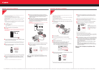
1
Remove the shipping tape from the
machine.
IMPORTANT
Make sure to remove the protective film from the
Feeder Cover.
2
Connect the telephone line and any
necessary external device.
Connect the telephone
line cord to the wall jack.
You can connect an external device
(telephone or answering machine) if necessary.
Connect external devices as follows:
External device jack
Telephone line jack
Telephone or answering machine
Built-in computer modem and telephone
Telephone
line
Telephone
line
Machine
Machine
Telephone or
answering machine
Telephone
Computer
LINE TEL
IMPORTANT
Be sure to use the bundled telephone line cable.
3
Plug the power cord into the back of
the machine and connect the other
end to a power outlet. Press [ON/OFF].
4
Use [
] or [
] on the Operation
Panel to select the language for the
LCD, then press [OK].
If the message <SET INK CARTRIDGE>
appears, go to
5
.
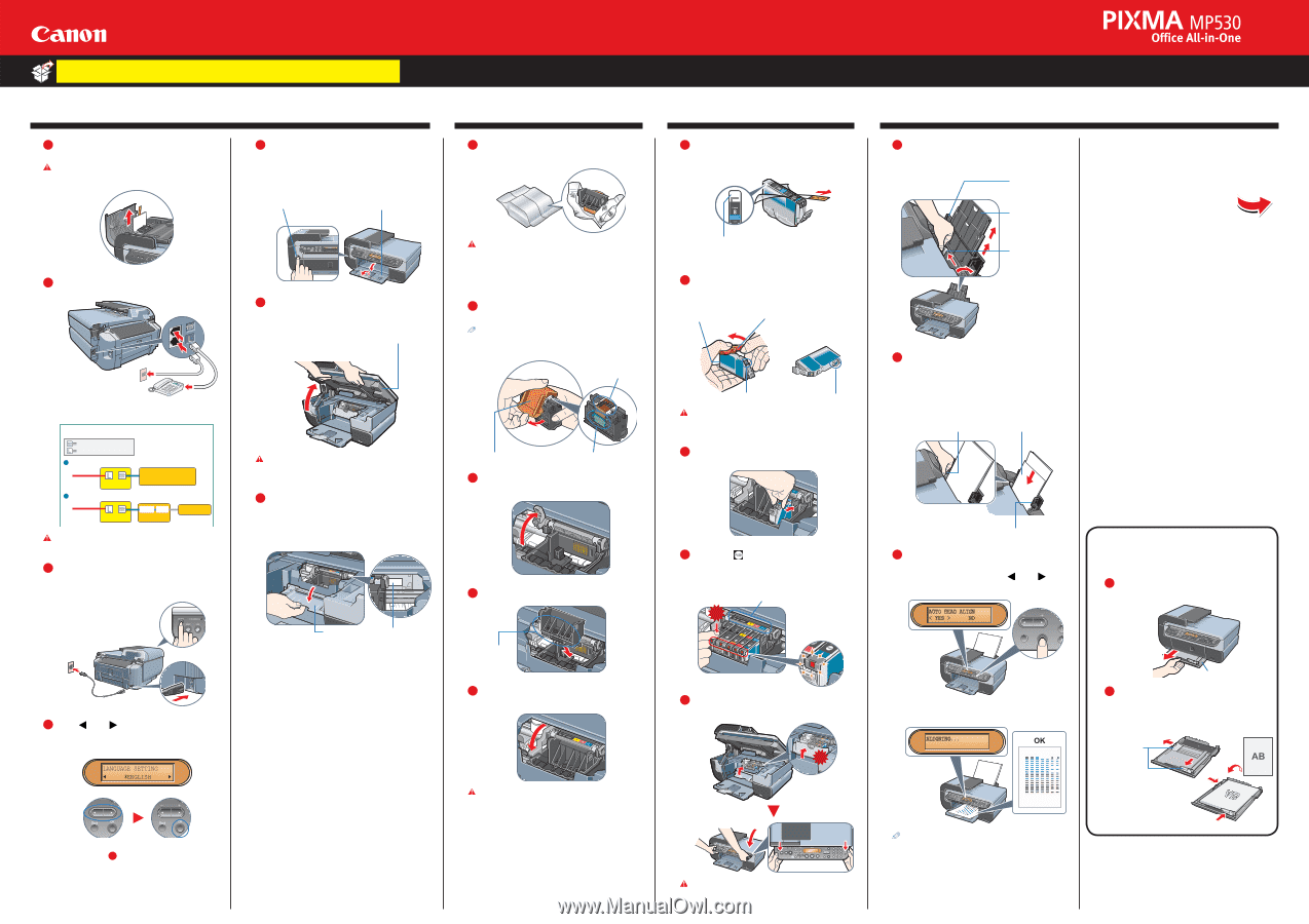
1
Prepare the machine
2
Install the Print Head
3
Install the ink tanks
4
Align the Print Head
5
Press the Open button to open the
Paper Output Tray. Open up and set
the Paper Output Tray extension by
pressing down the hollow on its front
side.
Paper Output Tray
Open Button
6
Open the Scanning Unit (Printer Cover)
until it locks into place. The Print Head
Holder moves to the center.
Scanning Unit (Printer Cover)
IMPORTANT
Be careful not to touch the buttons on the Operation
Panel.
7
Open the Inner Cover. Write down
the serial number located inside the
machine. You will need this to register
your products.
Inner Cover
Serial Number
Location
1
Remove the Print Head from its
package.
CAUTION
There might be some transparent or light blue ink on
the inside of the bag the print head comes in - this has
no effect on print quality. Be careful not to get ink on
yourself when handling these items.
2
Remove the orange protective cap
from the Print Head and discard it.
Do not touch the Print Head nozzles and the electrical
contacts.
Print Head
Nozzles
Electrical Contacts
Protective Cap
3
Firmly raise the Print Head Lock Lever
until it stops.
4
Insert the Print Head.
Do not
touch!
5
Lower the Print Head Lock Lever
carefully and press it down.
IMPORTANT
If the Scanning Unit (Printer Cover) is left open for
more than 10 minutes, the Print Head Holder moves to
the right. Close and reopen the Scanning Unit (Printer
Cover) to return the Holder to the center.
1
Peel back the orange tab completely
and remove the plastic wrapper from
the ink tank.
If the orange-colored protective film is
not removed completely, problems with
printing may occur.
2
Twist off and discard the orange
protective cap located on the bottom
of the ink tank.
Electrical Contacts
ink port
Protective Cap
Do not press!
IMPORTANT
• Do not touch the electrical contacts.
• Do not touch the ink port.
3
Insert the ink tank into the right-hand
slot.
4
Press the
mark on the ink tank until
it clicks into place and then its lamp
lights red.
Refer to the color guide on
the Print Head Lock Lever.
Click
5
Close the Inner Cover and the
Scanning Unit (Printer Cover).
Click
IMPORTANT
For safety, always firmly grip the areas illustrated
when closing the Scanning Unit (Printer Cover).
1
Open the Paper Support, then pull out
the extension. Pinch the Paper Guide
and slide it to the left.
Paper Support
Extension
Paper Guide
2
Load a few sheets of letter- or A4-size
paper into the Auto Sheet Feeder,
align the paper with the right side of
the Cover Guide, then slide the Paper
Guide toward the left edge of the
paper.
Print Side
Paper Guide
Cover Guide
3
Ensure that the message requesting
head alignment is displayed on the
LCD, select <YES> using [
] or [
]
and press [OK].
The pattern is printed. And Print Head is aligned
automatically.
• The pattern is printed in black and blue.
• Print Head alignment will take several minutes to
complete. Do not start another operation here.
• When automatic Print Head alignment cannot be executed
correctly, the message <HEAD ALIGNMENT ERROR>
is displayed on the LCD. Refer to “An Error Message is
Displayed on the LCD” in the
User’s Guide
.