Canon PIXMA iP5200 Service Manual - Page 17
Repair, 3-1. Notes on Service Part Replacement - reset
 |
View all Canon PIXMA iP5200 manuals
Add to My Manuals
Save this manual to your list of manuals |
Page 17 highlights
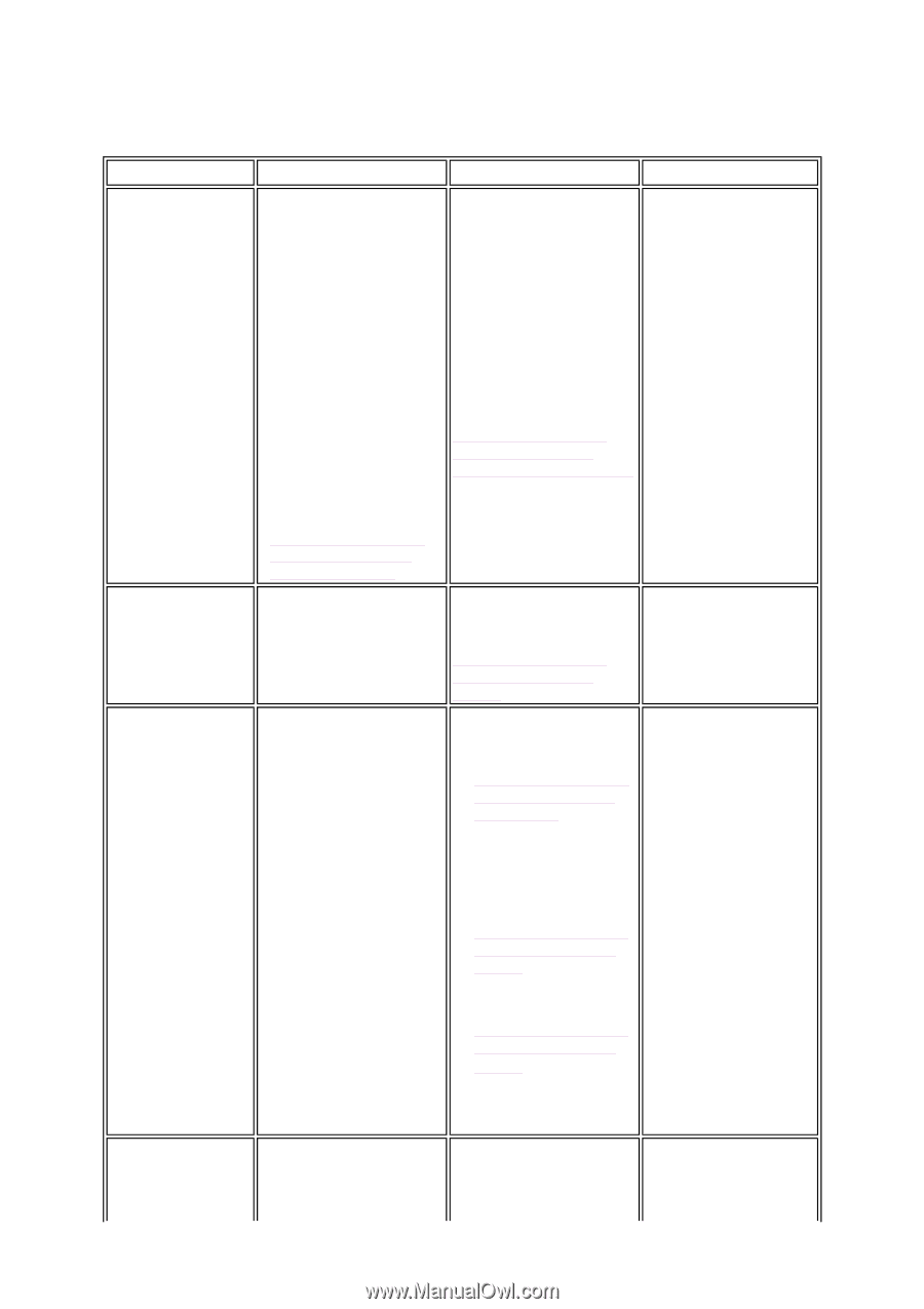
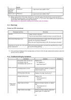
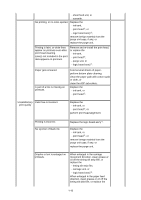
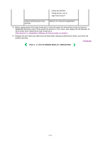
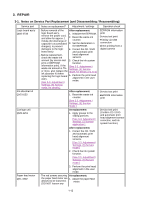
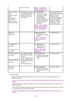
3. REPAIR 3-1. Notes on Service Part Replacement (and Disassembling / Reassembling) Service part Notes on replacement*1 Adjustment / settings Operation check Logic board ass'y QM2-2733 Ink absorber kit QY5-0152 Carriage unit QM2-2251 Paper feed motor QK1-1502 - Before removal of the After replacement: - EEPROM information logic board ass'y, remove the power cord, and allow for approx. 1 minute (for discharge of capacitor's accumulated charges), to prevent 1. Initialize the EEPROM. 2. Reset the waste ink counter. 3. Set the destination in the EEPROM. print - Service test print - Printing via USB connection - Direct printing from a damages to the logic 4. Correct the CD / DVD digital camera board ass'y. and automatic print - Before replacement, check the waste ink head alignment sensors. amount (by service test 5. Check the ink system print or EEPROM function. information print). If the [See 3-3. Adjustment / waste ink amount is 7% Settings, (5) Service or more, also replace the mode, for details of 1 to 5] ink absorber kit when replacing the logic board 6. Perform the print head ass'y. alignment in the user mode. [See 3-3. Adjustment / Settings, (5) Service mode, for details.] After replacement: 1. Reset the waste ink counter. [See 3.3. Adjustment / Settings, (5) Service mode.] - Service test print - EEPROM information print At replacement: 1. Apply grease to the sliding portions. [See 3-3. Adjustment / Settings, (2) Grease application.] - Service test print (Confirm CD / DVD and automatic print head alignment sensor correction, and ink system function.) After replacement: 1. Correct the CD / DVD and automatic print head alignment sensors. [See 3.3. Adjustment / Settings, (5) Service mode.] 2. Check the ink system function. [See 3.3. Adjustment / Settings, (5) Service mode.] 3. Perform the print head alignment in the user mode. - The red screws securing At replacement: the paper feed motor are 1. Adjust the paper feed allowed to be loosened. motor. (DO NOT loosen any 1-12
-
 1
1 -
2
-
3
-
4
-
5
-
6
-
7
-
8
-
9
-
10
-
11
-
 12
12 -
 13
13 -
 14
14 -
 15
15 -
 16
16 -
 17
17 -
 18
18 -
 19
19 -
 20
20 -
 21
21 -
 22
22 -
23
-
24
-
25
-
26
-
27
-
28
-
29
-
30
-
31
-
32
-
33
-
34
-
35
-
36
-
37
-
38
-
39
-
40
-
41
-
42
-
43
-
44
-
45
-
46
-
47
-
48
-
49
-
50
-
51
-
52
-
53
-
54
-
55
-
56
-
57
-
58
-
59
-
60
-
61
-
62
-
63
-
64
 |
 |