Canon VB-M640VE Network Camera VB-M641VE / VB-M640VE Installation Guide
Canon VB-M640VE Manual
 |
View all Canon VB-M640VE manuals
Add to My Manuals
Save this manual to your list of manuals |
Canon VB-M640VE manual content summary:
- Canon VB-M640VE | Network Camera VB-M641VE / VB-M640VE Installation Guide - Page 1
Guide (This document) Notice Dedicated wrench Symbols Indicating Camera Model Camera specific functions will be listed using the symbols below. : VB-M641VE : VB-M640VE © CANON instructions accompanied by this symbol may result in injury. Caution Failure to follow the instructions service Manual - Canon VB-M640VE | Network Camera VB-M641VE / VB-M640VE Installation Guide - Page 2
manual VB (sold separately) . PoE, 12 V DC and AC Adapters can not be used. PoE (Power over Ethernet) The camera supports the instruction guide service or visit www.canon-europe.com/weee, or www. canon-europe.com/battery. CANON INC. 30-2, Shimomaruko 3-chome, Ohta-ku, Tokyo 146-8501, Japan CANON
-
 1
1 -
 2
2
 |
 |

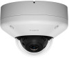
Network Camera
/
Installation Guide
Please be sure to read the “Safety Precautions” section for correct use. After reading this Installation
Guide, keep it in a readily accessible location for future reference.
* Some cameras are not available in certain countries or regions.
Caution
Request a professional installer for all installation work. Never try to install the camera yourself.
Doing so may result in unforeseen accidents such as dropping the camera or electric shock.
Check Included Items
Camera, Screws (M4) x 4
Template
Installation Guide (This document)
Setup CD-ROM
Warranty Card
Notice
Ceiling Plate
Safety Wire, Screws (M4) x 1
Dedicated wrench
Power Interface Cable
I/O Interface Cable (BK2-0035-000)
Symbols Indicating Camera Model
Camera specific functions will be listed using the symbols below.
: VB-M641VE
: VB-M640VE
BIE-7068-000
© CANON INC. 2015
Printed in Japan
Symbols Indicating Safety Precautions
This Installation Guide uses the following symbols to indicate important information the user should know in order
to use the product safely. Explanations are provided for each symbol so that users will understand the level of
importance for each. Be sure to observe these items.
Warning
Failure to follow the instructions accompanied by this symbol may result in death or
serious injury.
Caution
Failure to follow the instructions accompanied by this symbol may result in injury.
Caution
Failure to follow the instructions accompanied by this symbol may result in property
damage.
Important
This symbol indicates important or restricted items.
Note
Contains reference information for operation or additional explanations.
Safety Precautions
Installation Precautions
Warning
Do not install in the following places:
•
Places in strong direct sunlight, near heat-generating objects, or locations subject to high
temperatures
•
Places near fire sources or flammable solvents (alcohol, thinner, fuel, etc.)
•
Places subject to oily smoke or steam
•
Confined or enclosed places
Failure to do so may result in fire or electric shock.
•
Insulate the ends of cables you are not using.
Failure to insulate will cause fire or electric shock.
Notes on Power Supply
•
Only use the dedicated AC adapter (sold separately) for AC power.
•
Do not set any heavy objects on the power cable (or the LAN cable for a PoE power supply).
•
Do not pull, forcibly bend, scratch, or modify the power cable (or the LAN cable for a PoE power
supply).
•
Do not cover or wrap the AC adapter (sold separately) with cloth or blankets.
Failure to do so may result in fire or electric shock.
Caution
For installation or inspection of this camera, consult the dealer where you purchased the product.
•
This installation should be made by a qualified service person and should conform to all local codes.
•
When installing, make sure the surface is capable of withstanding the total weight of the camera and
accessories, and that it is sufficiently reinforced.
•
Be sure to use installation screws designed for the type of surface the camera is to be installed.
•
Periodically check the parts and screws for rust and loosening, in order to prevent injuries and
equipment damage due to falling items.
•
Do not install in unstable places, places subject to significant vibration or impact, or places subject to
salt damage or corrosive gas.
•
Do not install in places subject to strong winds.
•
Do not install where snow can accumulate directly on the camera.
•
Be sure to attach the safety wire when installing the camera.
Failure to do so may result in the camera falling or other accidents.
•
Do not touch the edges of metal parts with bare hands.
•
Take care not to catch your fingers when installing.
Failure to do so may result in injuries.
Caution
•
Do not move the lens unit by hand.
•
Do not install on an unstable surface.
•
To maximize shock resistant specifications, do not install on insufficiently strong surfaces or surfaces
subject to significant vibration.
•
After turning off the power, do not turn the power on again for at least five seconds.
•
Take measures to remove static electricity before performing any procedures.
•
If there is condensation, please wait to power on, until the condensation dissipates.
•
Please waterproof and dust-proof camera as necessary, when installing outdoors.
Failure to do so may result in malfunctions.
•
Take care not to damage wiring or piping.
Failure to do so may result in damage to peripheral items.
Important
•
We recommend the installation of a lightning arrester (a surge protection device) as a measure against failures caused by
lightning strikes. Please refer to our website for details.
Precautions for Installing the Camera Outdoor
When installing the camea outdoors, observe the following precautions to retain
waterproof/dustproof capabilities.
.
•
・Use the sunshade cover (sold separately) when installing in a location with direct
sunlight.
•
・Waterproof the cable connections and the ends of cables you are not using, including
their connectors.
•
・When mounting the camera onto a wall or other upright surface, position the cables
straight down to prevent rain infiltration.
•
・If wiring by connecting the camera to the composite pipe (3/4 inch NPSM threaded
hole), bridge the gap using the conduit adapter (sold separately). When connecting
the conduit adapter and the pipe, wrap Teflon tape around the tip of the pipe
to prevent water getting in as necessary, clear any debris, and firmly tighten. If
necessary, apply silicon sealant to seal it tightly after attaching the pipe.
•
Firmly fix the dome case to the main unit of the camera with the lock screws, taking
care not to pinch cables between the main unit and dome case.
Precautions for Use
Warning
•
If you discover defective conditions such as smoke, strange sounds, heat or strange odors,
immediately stop using the camera and contact your nearest dealer.
Fire or electric shock may result from continued use of the product.
•
If thunder starts, stop installation or inspection etc. and do not touch the camera or continue
connecting the cable.
•
Do not disassemble or modify the camera.
•
Do not damage the connecting cable.
•
Do not insert foreign objects such as water or metal into the camera.
•
Do not use flammable sprays near the camera.
•
Do not leave LAN cables, external power supply, or the power connector for the AC adapter (
sold
separately
) connected when the camera is not in use for long periods.
•
Do not use flammable solvents such as alcohol, paint thinner or benzine when cleaning the camera.
Failure to do so may result in fire or electric shock.
Specifications
Please refer to the installation procedures or the Appendix – Specifications for specifications not listed below.
Camera
Lens
2.4 optical zoom (4x digital zoom) lens (electric drive)
Viewing Angle
For 16:9 aspect ratios
Horizontal: 111.5° (W) – 46.2° (T)
Vertical: 60.5° (W) – 25.9° (T)
For 4:3 aspect ratios
Horizontal: 111.5° (W) – 46.2° (T)
Vertical: 81.7° (W) – 34.6° (T)
Min. Subject Illumination
Day Mode (color):
0.02 lux (F1.2, shutter speed 1/30 sec., when smart shade control is off, 50IRE)
Night Mode (monochrome):
0.001 lux (F1.2, shutter speed 1/30 sec., when smart shade control is off, 50IRE)
When using the Dome Unit (Smoked) (sold separately)
Day Mode (color):
0.04 lux (F1.2, shutter speed 1/30 sec., when smart shade control is off, 50IRE)
Night Mode (monochrome):
0.002 lux (F1.2, shutter speed 1/30 sec., when smart shade control is off, 50IRE)
Pan Angle Range
350° (±175°)
Tilt Angle Range
150° (±75°)
Rotation Angle Range
350° (±175°)
Interface
Network Terminal
LAN x 1 (RJ45, 100Base-TX (auto/full-duplex/half-duplex))
Audio Input Terminal
3.5 mm (
0.14 in.) mini-jack connector (monaural)
(Common for LINE IN & MIC IN)
LINE IN (connect to an amplifier microphone) or
MIC IN (connect to a microphone w/o amplifier)
Switch LINE IN/MIC IN in the setting page.
Audio Output Terminal
3.5 mm (
0.14 in.) mini-jack connector (monaural)
(LINE OUT)
LINE OUT (connect to an amplifier speaker)
External Device I/O Terminal
Input x 2, Output x 2
Memory Card *
microSD Memory Card, microSDHC Memory Card, microSDXC Memory Card Compatible.
Recorded Content: Log, Video (Event, Manual, ONVIF, Timer, Upload
)
Frame Rate: Max. 1 fps (JPEG)
Max. 30 fps (H.264)
* Use Class 10 cards. Cards under Class 10 may not have sufficient performance for tasks such as video
recording.
Others
Operating Environment
Temperature:
– Sunshade Cover (sold separately) necessary when under direct sun exposure
When the heater unit (sold separately) is installed
AC: -40°C – +55°C
(-40°F – +131°F)
DC, PoE: -10°C – +55°C
(+14°F – +131°F)
Start-up Temperature Range (including direct sun exposure) :
AC: -30°C – +55°C (-22°F – +131°F)
DC, PoE: -10°C – +55°C
(+14°F – +131°F)
When the heater unit (sold separately) is not installed
AC, DC, PoE: -10°C – +55°C
(+14°F – +131°F)
Humidity: 5% – 85% (without condensation)
Temperature:
PoE: -10°C – +55°C
(+14°F – +131°F)
–
Sunshade Cover (sold separately) necessary when under direct sun exposure
Humidity: 5% – 85% (without condensation)
Storage Environment
Temperature: -30°C – +60°C (-22°F – +140°F)
Humidity: 5% – 90% (without condensation)
Installation Method
Ceiling mount/Surface mount
Power Supply
PoE: PoE power supply via LAN connector (IEEE802.3at Type1 compliant)
AC Adapter: PA-V18 (100 – 240 V AC) (sold separately)
External power source: 24 V AC/12 V DC
PoE: PoE power supply via LAN connector (IEEE802.3at Type1 compliant)
Power Consumption
PoE: Max. approx. 8.9 W
AC Adapter PA-V18: Max. approx. 10.5 W (100 V AC)
Max. approx. 10.6 W (240 V AC)
DC: Max. approx. 9.5 W
AC: Max. approx. 9.1 W
Max. approx. 21.7 W*
* When the heater unit (sold separately) is installed
PoE: Max. approx. 8.9 W
Weight
Approx. 1620 g (3.58 lb.)
Approx. 1590 g (3.51 lb.)
Conduit Adapter
(sold separately)
Impact Resistance
IK10 (20J)
Dust-resistant/
Waterproof Specification
IP66 rated
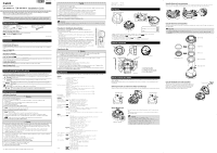
Part Names
2
4
5
6
10
11
9
3
1
13
12
8
7
Serial_ _ _ _ _ _ _ _ _ _ _ _ _ _ _ _ _
MAC_ _ _ _ _ _ _ _ _ _ _ _ _ _ _ _ _ _
1. Dome case lock screw / 2. Interface cover / 3. Dome case / 4. LED / 5. Lens unit / 6. Reset switch /
7. Reboot switch / 8. Memory card slot / 9. Power connection terminal
/
10. External device I/O terminals
/
11. Audio input terminal (Black) (common LINE IN and MIC IN)
/
12. Audio output terminal (White) (LINE OUT)
/ 13. 100Base-TX LAN connector
External Dimensions
180
(7.09)
R50 (R1.97)
Unit: mm (in.)
Unit: mm (in.)
Camera mounting tab slots
Camera mounting tabs
131 (5.16)
4.5 (0.18)
4.5 (0.18)
4.5 (0.18)
18.5 (0.73)
85.7 (3-3/8)
(*4)
85.7 (3-3/8)
(*3)
46.0 (1-13/16)
(*4)
10-
4.5 (
0.18)
(*1, *2)
4-M4
(*5)
4.8
(0.19)
172 (6.77)
83.5 (3-9/32)
(*4)
85.7 (3-3/8)
(*3, *4)
*1 Ceiling/Wall mount holes
*2 Junction box fixing holes
*3 Ceiling/Wall mount holes position
*4 Junction box fixing holes position
*5 Camera mounting holes
Before installing the camera
Set the IP address and other network information on the camera using the “Camera Management Tool” on the
Setup CD-ROM.
For details on how to operate the “Camera Management Tool”, please refer to the
“Camera Management Tool
User Manual”.
Removing the dome case and the lens rotation prevention tape
Remove the dome case, then remove the tape preventing the lens from rotating which was attached for shipping.
❶
❷
❸
❺
❹
Dedicated wrench
Dedicated wrench
Using a Memory Card
Remove the dome case and place the memory card in the memory card
slot.
To remove the memory card, push it in all the way until the card slightly
pops out and remove.
Important
•
Insert a memory card before installing the camera.
•
When using a memory card with the camera for the first time, it is
recommended to format the card after inserting it into the camera (please refer
to “Operation Guide” > “Setting Page” > “Memory Card”).
•
Always unmount the memory card before removing it (please refer to
“Operation Guide” > “Setting Page” > “Memory Card”).
Memory card slot
ENGLISH
Accessories
The following accessories can be purchased separately as necessary. Some accessories are not available in
certain countries or regions.
Pendant Mounting Kit PC640-VB
Dedicated accessory used to install the camera to the end of pipe that extends from high ceilings, such as in big-box
stores.
Dome Unit DU640-S-VB
Smoked dome cover.
Sunshade Cover SC640-VB
Dedicated accessory to protect the camera body from direct sunlight.
Heater Unit HU641-VB
Dedicated accessory
attached to the interior of VB-M641VE to maintain operation temperature within the dome and
achieve stable operation even in extremely cold environments.
Conduit Adapter CA640-VB
Dedicated accessory used to protect the wiring cable to connect the pipe and the body.
Canon AC Adapter PA-V18
Dedicated AC adapter for this camera.
Using the Heater Unit (sold separately)
Connect the two heater cables included with the heater unit, to the terminals on the camera side. Next, attach the
heater unit to the camera body and then tighten the screws. Finally, connect the cables to the heater unit.
❶
❸
❷
Using the Dome Unit (sold separately)
Remove the dome case from the camera, then remove the dome cover holder and dome flange, and replace with
the smoked dome.
Important
•
Take care when replacing so as not to scratch the dome cover.
•
For proper protection against water and dust, please make sure the screws are firmly tightened during
installation.
Dome flange
Dome cover
Rubber seal
Dome cover holder
Dedicated wrench
Smoked dome cover
Using the Sunshade Cover (sold separately)
The sunshade cover is attached to the camera body together with
the dome case. In order to install it, of the four lock screws for the
dome case, remove the two located at the top of the dome case
beforehand. The dome case lock screws can be removed by
pressing and loosening from the inside of the case.
Dedicated wrench
The contents of this guide are subject to change without any prior notice.