Canon VB-M740E Network Camera VB-M741LE / VB-M740E Installation Guide
Canon VB-M740E Manual
 |
View all Canon VB-M740E manuals
Add to My Manuals
Save this manual to your list of manuals |
Canon VB-M740E manual content summary:
- Canon VB-M740E | Network Camera VB-M741LE / VB-M740E Installation Guide - Page 1
the "Camera Management Tool", please refer to the "Camera Management Tool User Manual". Using a Memory Card Loosen the screws with the dedicated wrench, open attached to the composite pipe. Please refer to the installation guide included with the conduit box for the installation method. Dedicated - Canon VB-M740E | Network Camera VB-M741LE / VB-M740E Installation Guide - Page 2
to read the user manual for the dedicated power more information, check the instruction guide for your PoE+/PoE HUB problems such as unstable network connections. If a problem single audio input system, it supports two types of microphone input: your household waste disposal service or visit www.
-
 1
1 -
 2
2
 |
 |
Network Camera
/
Installation Guide
Please be sure to read the “Safety Precautions” section for correct use. After reading this
Installation Guide, keep it in a readily accessible location for future reference.
* Some cameras are not available in certain countries or regions.
Caution
Request a professional installer for all installation work. Never try to install the
camera yourself. Doing so may result in unforeseen accidents such as dropping
the camera or electric shock.
Check Included Items
Camera, Screws (M4) x 4
Template
Installation Guide (This document)
Setup CD-ROM
Warranty Card
Ceiling Plate
Notice
Dedicated wrench
Safety Wire, Screws (M3) x 1
I/O Interface Cable
(BK2-0035-000)
Power Interface Cable
Symbols Indicating Camera Model
Camera specific functions will be listed using the symbols below.
: VB-M741LE
: VB-M740E
Accessories
The following accessories can be purchased separately as necessary. Some accessories are not
available in certain countries or regions.
Conduit Box CB740-VB
Dedicated accessory used to protect wiring cables that cannot be stored above the ceiling. This can
be attached to the composite pipe.
Pendant Mounting Kit PC640-VB
Dedicated accessory used to install the camera to the end of pipe that extends from high ceilings,
such as in big-box stores.
Canon AC Adapter PA-V18
Dedicated AC adapter for this camera.
BIE-7069-000
© CANON INC. 2015
Printed in Japan
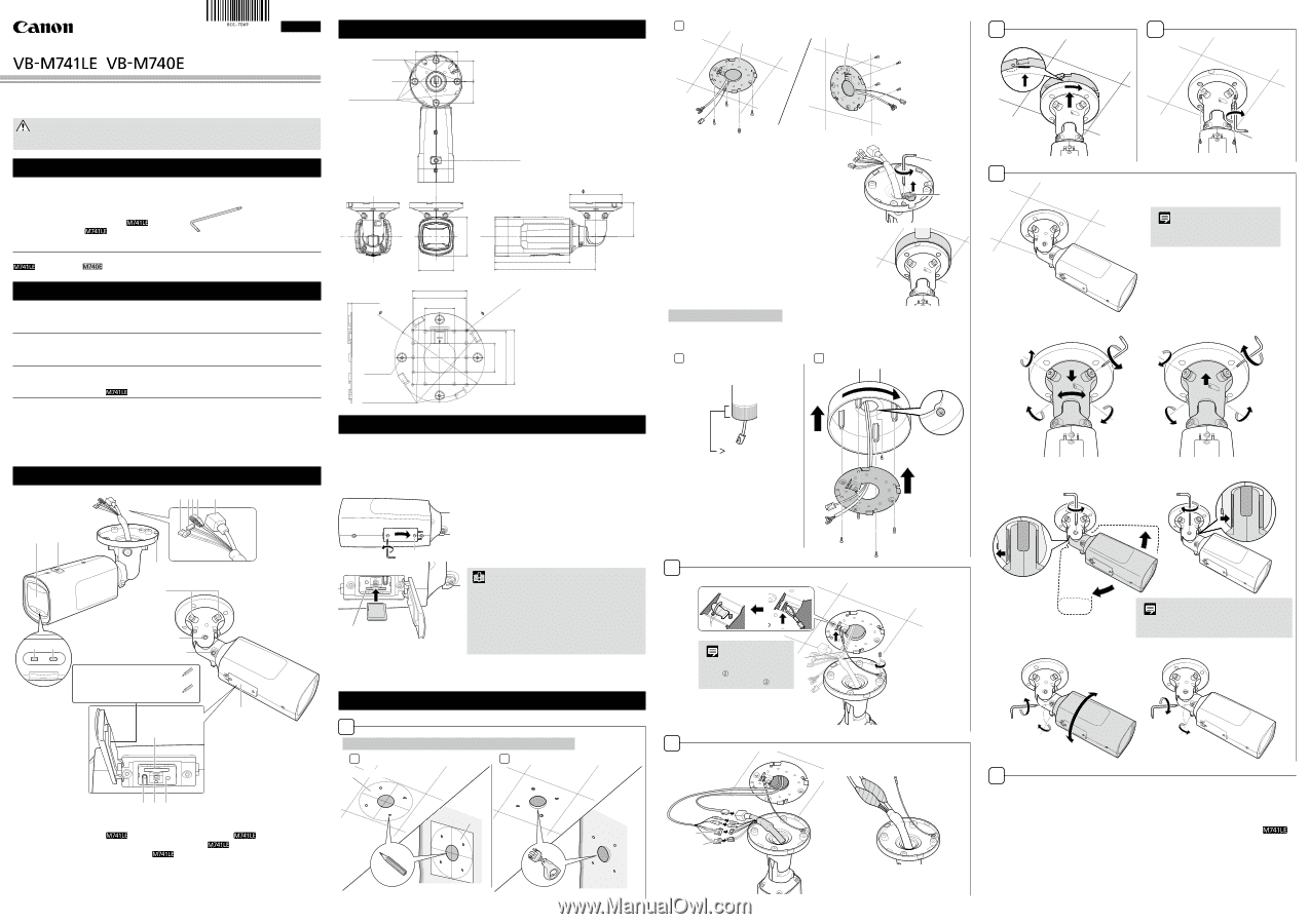
Part Names
2
7
12
11
18
3
4
1
6
8
9
10
13
5
14
15
16
17
Serial_ _ _ _ _ _ _ _ _ _ _ _ _ _ _ _ _
MAC_ _ _ _ _ _ _ _ _ _ _ _ _ _ _ _ _ _
1. Lens protector / 2. Screw hole for attaching / 3. LED (Orange) / 4. LED (Blue) / 5. Notched cap /
6. Power connection terminal
/ 7. External device I/O terminals
/
8. Audio input terminal (Black) (common LINE IN and MIC IN)
/
9. Audio output terminal (White) (LINE OUT)
/ 10. 100Base-TX LAN connector
11. Pan axis adjustment screw / 12. Tilt axis adjustment screw /
13. Rotation axis adjustment screw / 14. Memory card slot / 15. Reset switch / 16. LED (Blue) /
17. Reboot switch / 18. Memory card cover
External Dimensions
Unit: mm (in.)
Unit: mm (in.)
Camera mounting
tab slots
Camera
mounting tabs
111 (4.37)
102 (4.02)
60 (2.36)
60 (2.36)
60 (2.36)
60 (2.36)
96 (3.78)
214 (8.43)
288 (11.34)
85.7 (3-3/8)
(*3, *4)
83.5 (3-9/32)
(*4)
46.0 (1-13/16)
(*4)
85.7 (3-3/8)
(*3, *4)
83.5 (3-9/32)
(*4)
46.0 (1-13/16)
(*4)
14-
4.5 (0.18)
(*5, *6)
7.0 (0.28)
151 (5.94)
142 (5.59)
Screw hole for attaching
4-M4
(*1, *2)
4-M4
(*7)
*1 Ceiling plate mount holes
*2 Option unit mount holes
*3 Ceiling/Wall mount holes position
*4 Junction box fixing holes position
*5 Ceiling/Wall mount holes
*6 Junction box fixing holes
*7 Camera mounting holes
Before installing the camera
Set the IP address and other network information on the camera using the “Camera Management
Tool” on the Setup CD-ROM.
For details on how to operate the “Camera Management Tool”, please refer to the
“Camera
Management Tool User Manual”.
Using a Memory Card
Memory card slot
Loosen the screws with the dedicated wrench, open the
memory card cover, and then place the memory card in
the memory card slot. Once the memory card is in place,
close the memory card cover and tighten the screws
with the dedicated wrench.
To remove the memory card, push it in all the way until
the card slightly pops out and remove.
Important
•
Insert a memory card before installing the camera.
•
When using a memory card with the camera for the first
time, it is recommended to format the card after inserting
it into the camera (please refer to the “Operation Guide” >
“Setting Page” > “Memory Card”).
•
Always unmount the memory card before removing it
(please refer to the “Operation Guide” > “Setting Page” >
“Memory Card”).
Once this has been completed, close the memory card cover and tighten the screws with the
dedicated wrench.
ENGLISH
4
5
Dedicated
wrench
M4 × 4
Screws
(included)
6
Use the dedicated wrench to adjust the
following three rotation axes to set the angle.
Note
Set the angle so that the memory card
cover is at the bottom.
Adjusting the pan axis
❶
❷
❸
❹
❺
Adjusting the tilt axis
❶
❷
❸
❹
Note
Shake the unit after tightening the screws. If the joint
section appears to wobble, further tighten the screw.
Adjusting the rotation axis
❶
❷
❸
7
When the installation has finished, please adjust the angle using the “Camera Angle Setting
Tool”, found in the Setup CD-ROM.
When the temperature within the camera is low (heater activated)
When the unit is powered by a 24 V AC/ PoE+ power source, the heater unit can be used.
The heater unit’s orange LED will turn on, when the unit has been activated due to the low
temperature within the camera, and the transfer of video is also not possible.
Once the temperature within the camera has reached the level where it can transfer the video
once again, the orange LED will turn off.
Installing the Camera
1
Directly attached to ceilings/Directly attached to walls
1 -1
1 -2
a
a
Ceiling Installation
Wall Installation
a.
Template
1 -3
b
b
b.
Ceiling Plate
If the cables cannot be stored above a ceiling
If the cables cannot be stored above the ceiling,
such as with concrete ceilings, remove the notched
cap at the camera joint section with the dedicated
wrench, and create an opening for the cable to pass
through.
The cables can be stored with the use of the conduit box
CB740-VB (sold separately), which can also be attached
to the composite pipe. Please refer to the installation guide
included with the conduit box for the installation method.
Ceiling pendant mounting
Mount using the Pendant Mounting Kit (sold separately).
For details please refer to the Installation Guide included with the kit.
1 -1
1 -2
Pass necessary cables for
connecting the camera through
the pipe.
2.5 cm (1.0 in.)
❶
❹
❸
❷
M4* × 4
* Included
with Pendant
Mounting Kit
M3*
2
c
❷
❸
❶
M3
Screws (included)
Note
Pass the safety wire through
the slit
and attach it to the
hook on the rear side
.
c.
Safety wire
3
Wrap the cable connection with
waterproof tape.
d
e
d.
I/O interface cable
e.
Power interface cable
Notched
cap
Dedicated
wrench
The contents of this guide are subject to change without any prior notice.