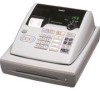
Casio PCRT275 Owners Manual - Page 2
Circuit Explanation - reset
 |
View all Casio PCRT275 manuals
Add to My Manuals
Save this manual to your list of manuals |
Page 2 highlights
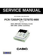
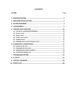
TE-M80 CONTENTS Page 1. SPECIFICATIONS 1 2. MACHINE INTIALIZATION 3 3. BLOCK DIAGRAM 4 4. DISASSEMBLY 5 5. CIRCUIT EXPLANATION 10 5-1. CPU (IC12: uPD784215AGC8038EU 10 5-2. Power circuit ...14 5-3. Reset circuit ...14 5-4. Printer drive circuit 15 5-5. Display circuit ...15 5-6. Winding motor circuit & Drawer circuit 16 6. DIAGNOSTIC OPERATIONS 17 6-1. Content of the Test ...17 6-2. Displaying the Key Code 17 6-3. Displaying the Switch Condition 18 6-4. Printing and Display test 19 7. TROUBLESHOOTING 21 8. IC DATA ...22 9. CIRCUIT DIAGRAM 23 10. PARTS LIST 28
-
 1
1 -
 2
2 -
 3
3 -
 4
4 -
 5
5 -
 6
6 -
 7
7 -
 8
8 -
9
-
10
-
11
-
12
-
13
-
14
-
15
-
16
-
17
-
18
-
19
-
20
-
21
-
22
-
23
-
24
-
25
-
26
-
27
-
28
-
29
-
30
-
31
-
32
-
33
-
34
-
35
-
36
-
37
-
38
-
39
-
40
-
41
-
42
-
43
-
44
-
45
-
46
-
47
 |
 |

CONTENTS
TE-M80
Page
1. SPECIFICATIONS
........................................................................................
1
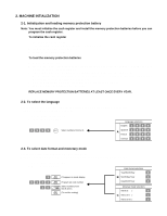
2.
MACHINE INTIALIZATION
..........................................................................
3
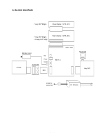
3.
BLOCK DIAGRAM
.......................................................................................
4
4. DISASSEMBLY
............................................................................................
5
5.
CIRCUIT EXPLANATION
..........................................................................
10
5-1.
CPU (IC12: uPD784215AGC8038EU)
.......................................................................
10
5-2.
Power circuit
.............................................................................................................
14
5-3.
Reset circuit
..............................................................................................................
14
5-4.
Printer drive circuit
...................................................................................................
15
5-5.
Display circuit
...........................................................................................................
15
5-6.
Winding motor circuit & Drawer circuit
..................................................................
16
6.
DIAGNOSTIC OPERATIONS
....................................................................
17
6-1. Content of the Test
....................................................................................................
17
6-2.
Displaying the Key Code
.........................................................................................
17
6-3.
Displaying the Switch Condition
.............................................................................
18
6-4.
Printing and Display test
.........................................................................................
19
7. TROUBLESHOOTING
...............................................................................
21
8.
IC DATA
.....................................................................................................
22
9.
CIRCUIT DIAGRAM
...................................................................................
23
10.
PARTS LIST
...............................................................................................
28