Cisco 1760 Hardware Installation Guide - Page 51
Removing a WIC or VIC Slot Cover, Warning, Caution, Step 1
 |
UPC - 746320684857
View all Cisco 1760 manuals
Add to My Manuals
Save this manual to your list of manuals |
Page 51 highlights
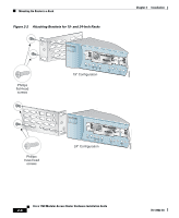
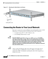
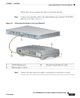
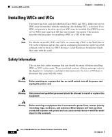
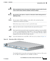
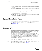
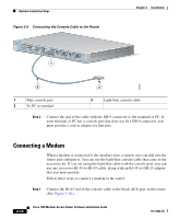
Chapter 2 Installation Installing WICs and VICs Warning Before opening the chassis, disconnect the telephone-network cables (from the card) to avoid contact with the telephone-network voltages. Warning Do not work on the system or connect or disconnect cables during periods of lightning activity. Caution Do not connect a WAN, telephone, or fax cable to the card until you have completed the installation procedure. Follow these steps to remove or insert a card in the router: Step 1 Make sure that the router is turned off and is disconnected from power. Caution Power must be disconnected from the system before installing or removing WICs or VICs to avoid damaging them. When WICs or VICs are pushed into or pulled out of a router that is powered up, there is a very good chance that they could be damaged electrically and will no longer function. Step 2 Loosen the thumbscrews on the WIC or VIC slot cover, as shown in Figure 2-6. Figure 2-6 Removing a WIC or VIC Slot Cover 60950 PWR OK PVDM 0 OK PVDM 1 OK MOD OK SLOT0 0 OK 1 SLOT1 0 OK 1 CONSOLE ACT COL FDX 100 LINK 10/100 ETHERNET AUX SLOT2 0 OK 1 SLOT3 0 OK 1 Cisco 1700 Series 78-13342-03 You should be able to loosen the screws using your fingers; however, if the screws are very tight, you might need to use a Phillips screwdriver. Cisco 1760 Modular Access Router Hardware Installation Guide 2-9
-
 1
1 -
2
-
3
-
4
-
5
-
6
-
7
-
8
-
9
-
10
-
11
-
12
-
13
-
14
-
15
-
16
-
17
-
18
-
19
-
20
-
21
-
22
-
23
-
24
-
25
-
26
-
27
-
28
-
29
-
30
-
31
-
32
-
33
-
34
-
35
-
36
-
37
-
38
-
39
-
40
-
41
-
42
-
43
-
44
-
45
-
 46
46 -
 47
47 -
 48
48 -
 49
49 -
 50
50 -
 51
51 -
 52
52 -
 53
53 -
 54
54 -
 55
55 -
 56
56 -
57
-
58
-
59
-
60
-
61
-
62
-
63
-
64
-
65
-
66
-
67
-
68
-
69
-
70
-
71
-
72
-
73
-
74
-
75
-
76
-
77
-
78
-
79
-
80
-
81
-
82
-
83
-
84
-
85
-
86
-
87
-
88
-
89
-
90
-
91
-
92
-
93
-
94
-
95
-
96
-
97
-
98
-
99
-
100
-
101
-
102
-
103
-
104
-
105
-
106
-
107
-
108
-
109
-
110
-
111
-
112
 |
 |