Cisco 1760 Hardware Installation Guide - Page 52
Step 3, Interface Card - router interfaces
 |
UPC - 746320684857
View all Cisco 1760 manuals
Add to My Manuals
Save this manual to your list of manuals |
Page 52 highlights
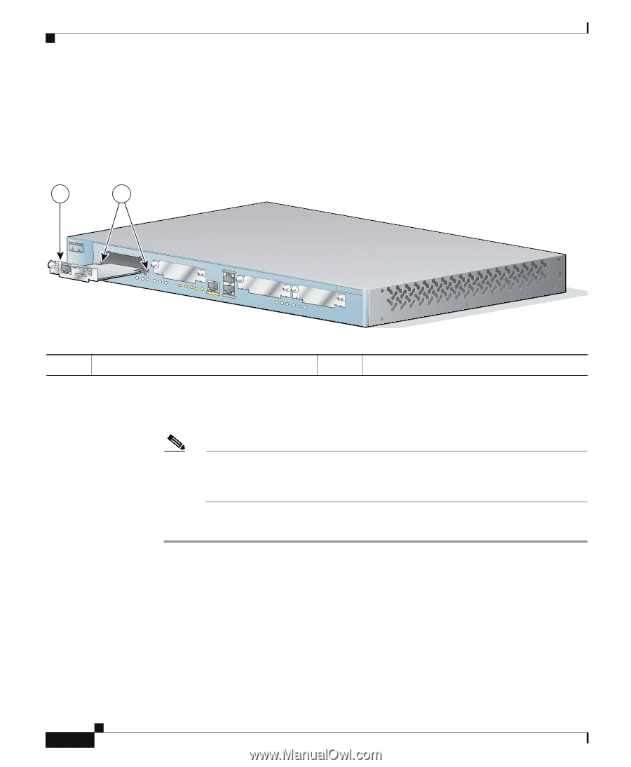
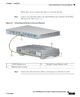
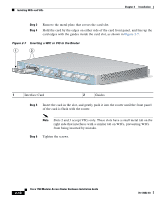
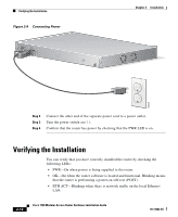
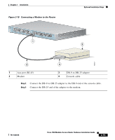
Installing WICs and VICs Chapter 2 Installation Step 3 Step 4 Remove the metal plate that covers the card slot. Hold the card by the edges on either side of the card front panel, and line up the card edges with the guides inside the card slot, as shown in Figure 2-7. Figure 2-7 Inserting a WIC or VIC in the Router 1 2 60949 PWR OK PVDM 0 OK PVDM 1 OK MOD OK SLOT0 0 OK 1 SLOT1 0 OK 1 CONSOLE ACT COL FDX 100 LINK 10/100 ETHERNET AUX SLOT2 0 OK 1 SLOT3 0 OK 1 Cisco 1700 Series 1 Interface Card 2 Guides Step 5 Insert the card in the slot, and gently push it into the router until the front panel of the card is flush with the router. Note Slots 2 and 3 accept VICs only. These slots have a small metal tab on the right side that interferes with a similar tab on WICs, preventing WICs from being inserted by mistake. Step 6 Tighten the screws. 2-10 Cisco 1760 Modular Access Router Hardware Installation Guide 78-13342-03
-
 1
1 -
2
-
3
-
4
-
5
-
6
-
7
-
8
-
9
-
10
-
11
-
12
-
13
-
14
-
15
-
16
-
17
-
18
-
19
-
20
-
21
-
22
-
23
-
24
-
25
-
26
-
27
-
28
-
29
-
30
-
31
-
32
-
33
-
34
-
35
-
36
-
37
-
38
-
39
-
40
-
41
-
42
-
43
-
44
-
45
-
46
-
 47
47 -
 48
48 -
 49
49 -
 50
50 -
 51
51 -
 52
52 -
 53
53 -
 54
54 -
 55
55 -
 56
56 -
 57
57 -
58
-
59
-
60
-
61
-
62
-
63
-
64
-
65
-
66
-
67
-
68
-
69
-
70
-
71
-
72
-
73
-
74
-
75
-
76
-
77
-
78
-
79
-
80
-
81
-
82
-
83
-
84
-
85
-
86
-
87
-
88
-
89
-
90
-
91
-
92
-
93
-
94
-
95
-
96
-
97
-
98
-
99
-
100
-
101
-
102
-
103
-
104
-
105
-
106
-
107
-
108
-
109
-
110
-
111
-
112
 |
 |