Cisco 1760 Hardware Installation Guide - Page 57
Step 2, Aux port RJ-45
 |
UPC - 746320684857
View all Cisco 1760 manuals
Add to My Manuals
Save this manual to your list of manuals |
Page 57 highlights
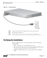
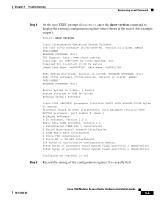
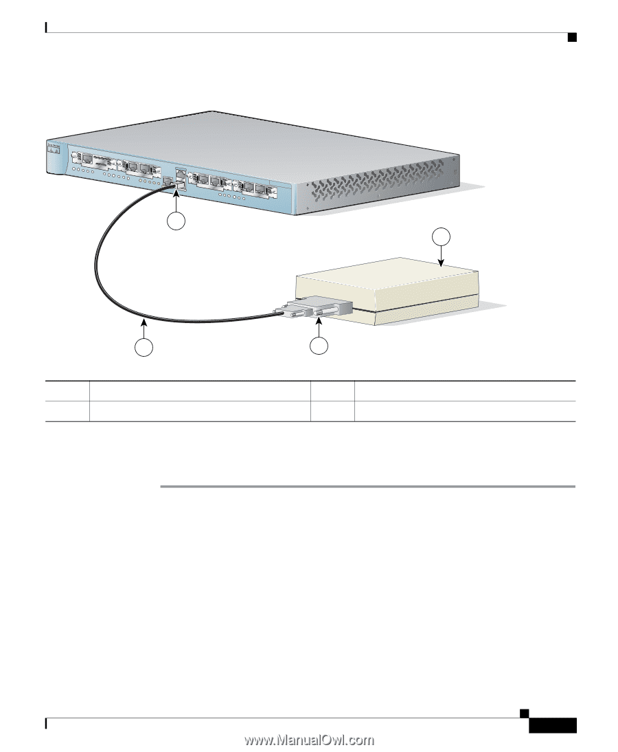
Chapter 2 Installation Figure 2-10 Connecting a Modem to the Router PWR OK PVDM 0 OK PVDM 1 OK MOD OK SLOT0 0 OK 1 SLOT1 0 OK 1 CONSOLE ACT COL FDX 100 LINK 10/100 ETHERNET AUX 1 SLOT2 0 OK 1 SLOT3 0 OK 1 Cisco 1700 Series Optional Installation Steps 2 60947 4 3 1 Aux port (RJ-45) 2 Modem 3 DB-9-to-DB-25 adapter 4 Console cable Step 2 Connect the DB-9-to-DB-25 adapter to the DB-9 end of the console cable. Step 3 Connect the DB-25 end of the adapter to the modem. 78-13342-03 Cisco 1760 Modular Access Router Hardware Installation Guide 2-15
-
 1
1 -
2
-
3
-
4
-
5
-
6
-
7
-
8
-
9
-
10
-
11
-
12
-
13
-
14
-
15
-
16
-
17
-
18
-
19
-
20
-
21
-
22
-
23
-
24
-
25
-
26
-
27
-
28
-
29
-
30
-
31
-
32
-
33
-
34
-
35
-
36
-
37
-
38
-
39
-
40
-
41
-
42
-
43
-
44
-
45
-
46
-
47
-
48
-
49
-
50
-
51
-
 52
52 -
 53
53 -
 54
54 -
 55
55 -
 56
56 -
 57
57 -
 58
58 -
 59
59 -
 60
60 -
 61
61 -
 62
62 -
63
-
64
-
65
-
66
-
67
-
68
-
69
-
70
-
71
-
72
-
73
-
74
-
75
-
76
-
77
-
78
-
79
-
80
-
81
-
82
-
83
-
84
-
85
-
86
-
87
-
88
-
89
-
90
-
91
-
92
-
93
-
94
-
95
-
96
-
97
-
98
-
99
-
100
-
101
-
102
-
103
-
104
-
105
-
106
-
107
-
108
-
109
-
110
-
111
-
112
 |
 |
2-15
Cisco 1760 Modular Access Router Hardware Installation Guide
78-13342-03
Chapter 2
Installation
Optional Installation Steps
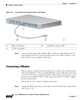
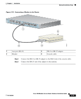
Figure 2-10
Connecting a Modem to the Router
Step 2
Connect the DB-9-to-DB-25 adapter to the DB-9 end of the console cable.
Step 3
Connect the DB-25 end of the adapter to the modem.
1
Aux port (RJ-45)
3
DB-9-to-DB-25 adapter
2
Modem
4
Console cable
Cisco 1700
Series
10/100 ETHERNET
AUX
CONSOLE
PVDM 0
OK
OK
PWR
1
0
SLOT 0
OK
PVDM 1
OK
MOD
OK
1
0
SLOT 1
OK
LINK
100
FDX
ACT
COL
1
0
SLOT 2
OK
1
0
SLOT 3
OK
1
3
4
2
60947