Cisco 1760 Hardware Installation Guide - Page 85
Opening the Chassis - max memory
 |
UPC - 746320684857
View all Cisco 1760 manuals
Add to My Manuals
Save this manual to your list of manuals |
Page 85 highlights
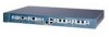
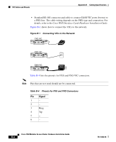
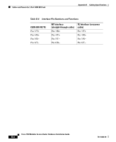
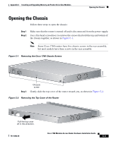
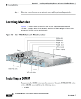
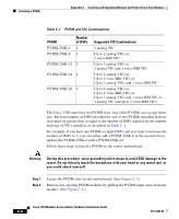
Appendix C Installing and Upgrading Memory and Packet Voice Data Modules Opening the Chassis Opening the Chassis Follow these steps to open the chassis: Step 1 Step 2 Make sure that the router is turned off and is disconnected from the power supply. Use a flat-head screwdriver to remove the screws that hold the top and bottom of the chassis together, as shown in Figure C-1. Note Some Cisco 1760 routers have five chassis screws in the rear assembly, but most models have three screws in the rear assembly. Figure C-1 Removing the Cisco 1760 Chassis Screws 1.5 M150A00X--6/2104.50HAVz~MAX 60956 Step 3 Chassis screw Gently slide the top cover of the router toward you, as shown in Figure C-2. Figure C-2 Removing the Top Cover of the Router 60957 1.5 M150A00X--6/2104.50HAVz~MAX Pull the top cover off in this direction. 78-13342-03 Cisco 1760 Modular Access Router Hardware Installation Guide C-3
-
 1
1 -
2
-
3
-
4
-
5
-
6
-
7
-
8
-
9
-
10
-
11
-
12
-
13
-
14
-
15
-
16
-
17
-
18
-
19
-
20
-
21
-
22
-
23
-
24
-
25
-
26
-
27
-
28
-
29
-
30
-
31
-
32
-
33
-
34
-
35
-
36
-
37
-
38
-
39
-
40
-
41
-
42
-
43
-
44
-
45
-
46
-
47
-
48
-
49
-
50
-
51
-
52
-
53
-
54
-
55
-
56
-
57
-
58
-
59
-
60
-
61
-
62
-
63
-
64
-
65
-
66
-
67
-
68
-
69
-
70
-
71
-
72
-
73
-
74
-
75
-
76
-
77
-
78
-
79
-
 80
80 -
 81
81 -
 82
82 -
 83
83 -
 84
84 -
 85
85 -
 86
86 -
 87
87 -
 88
88 -
 89
89 -
 90
90 -
91
-
92
-
93
-
94
-
95
-
96
-
97
-
98
-
99
-
100
-
101
-
102
-
103
-
104
-
105
-
106
-
107
-
108
-
109
-
110
-
111
-
112
 |
 |