Cisco 1760 Hardware Installation Guide - Page 90
Number, of DSPs, Supported VIC Combinations, Table C-1, C-3
 |
UPC - 746320684857
View all Cisco 1760 manuals
Add to My Manuals
Save this manual to your list of manuals |
Page 90 highlights
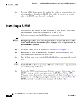
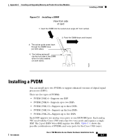
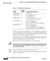
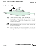
Installing a PVDM Appendix C Installing and Upgrading Memory and Packet Voice Data Modules Table C-1 PVDM and VIC Combinations PVDM PVDM-256K-4 PVDM-256K-8 Number of DSPs 1 2 PVDM-256K-12 3 PVDM-256K-16 4 PVDM-256K-20 5 Supported VIC Combinations 1 analog VIC Up to 2 analog VICs or 1 voice-BRI VIC Up to 3 analog VICs or 1 analog VIC and 1 voice-BRI VIC Up to 4 analog VICs or Up to 2 voice-BRI VICs or Up to 2 analog VICs and 1 voice-BRI VIC Up to 4 analog VICs or Up to 2 voice-BRI VICs or Up to 3 analog VICs and 1 voice-BRI VIC or 1 analog VIC and up to 2 voice-BRI VICs The Cisco 1760 router has two PVDM slots. Any of the PVDMs can occupy either slot. The total number of DSPs provided by one or two PVDMs installed in those slots must be greater than or equal to the number of DSPs required by the number and type of VICs installed, as described in Table C-1. For example, if you have one PVDM (a single DSP), and you want to increase the number of DSPs to 3, you can either add a PVDM-256K-8 in the second slot or replace the PVDM-256K-4 with a PVDM-256K-12. Follow these steps to install a PVDM on the router motherboard. Warning During this procedure, wear grounding wrist straps to avoid ESD damage to the router. Do not directly touch the backplane with your hand or any metal tool, or you could shock yourself. Step 1 Step 2 Locate the PVDM slots on the motherboard. (See Figure C-3.) Remove any existing PVDM modules by pulling the PVDM snaps away from the module. (See Figure C-6.) Cisco 1760 Modular Access Router Hardware Installation Guide C-8 78-13342-03
-
 1
1 -
2
-
3
-
4
-
5
-
6
-
7
-
8
-
9
-
10
-
11
-
12
-
13
-
14
-
15
-
16
-
17
-
18
-
19
-
20
-
21
-
22
-
23
-
24
-
25
-
26
-
27
-
28
-
29
-
30
-
31
-
32
-
33
-
34
-
35
-
36
-
37
-
38
-
39
-
40
-
41
-
42
-
43
-
44
-
45
-
46
-
47
-
48
-
49
-
50
-
51
-
52
-
53
-
54
-
55
-
56
-
57
-
58
-
59
-
60
-
61
-
62
-
63
-
64
-
65
-
66
-
67
-
68
-
69
-
70
-
71
-
72
-
73
-
74
-
75
-
76
-
77
-
78
-
79
-
80
-
81
-
82
-
83
-
84
-
 85
85 -
 86
86 -
 87
87 -
 88
88 -
 89
89 -
 90
90 -
 91
91 -
 92
92 -
 93
93 -
 94
94 -
 95
95 -
96
-
97
-
98
-
99
-
100
-
101
-
102
-
103
-
104
-
105
-
106
-
107
-
108
-
109
-
110
-
111
-
112
 |
 |
