Cisco 2960-48PST-L Hardware Installation Guide
Cisco 2960-48PST-L - Catalyst Switch Manual
 |
UPC - 882658220579
View all Cisco 2960-48PST-L manuals
Add to My Manuals
Save this manual to your list of manuals |
Cisco 2960-48PST-L manual content summary:
- Cisco 2960-48PST-L | Hardware Installation Guide - Page 1
Catalyst 2900 Series XL Hardware Installation Guide April 2002 Corporate Headquarters Cisco Systems, Inc. 170 West Tasman Drive San Jose, CA 95134-1706 USA http://www.cisco.com Tel: 408 526-4000 800 553-NETS (6387) Fax: 408 526-4100 Customer Order Number: DOC-786461= Text Part Number: 78-6461-04 - Cisco 2960-48PST-L | Hardware Installation Guide - Page 2
, and iQuick Study are service marks of Cisco Systems, Inc.; and Aironet, ASIST, BPX, Catalyst, CCDA, CCDP, CCIE, CCNA, CCNP, Cisco, the Cisco Certified Internetwork Expert logo, Cisco IOS, the Cisco IOS logo, Cisco Press, Cisco Systems, Cisco Systems Capital, the Cisco Systems logo, Empowering the - Cisco 2960-48PST-L | Hardware Installation Guide - Page 3
document or Web site are the property of their respective owners. The use of the word partner does not imply a partnership relationship between Cisco and any other company. (0201R) Catalyst 2900 Series XL Hardware Installation Guide Copyright © 1999-2002, Cisco Systems, Inc. All rights reserved. - Cisco 2960-48PST-L | Hardware Installation Guide - Page 4
- Cisco 2960-48PST-L | Hardware Installation Guide - Page 5
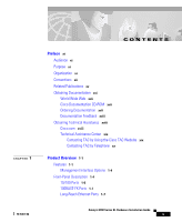
Contacting TAC by Using the Cisco TAC Website xix Contacting TAC by Telephone xx Product Overview 1-1 Features 1-1 Management Interface Options 1-4 Front-Panel Description 1-4 10/100 Ports 1-6 100BASE-FX Ports 1-7 Long-Reach Ethernet Ports 1-7 Catalyst 2900 Series XL Hardware Installation Guide v - Cisco 2960-48PST-L | Hardware Installation Guide - Page 6
1-21 Cisco RPS Connector 1-22 Console Port 1-23 Switch 2-11 Attaching the Brackets to a Catalyst 2912 XL, 2924C XL, 2924 XL, 2912MF XL, 2924M XL, or 2924M XL DC Switch 2-11 Attaching the Brackets to a Catalyst 2912 LRE XL or 2924 LRE XL Switch 2-16 Catalyst 2900 Series XL Hardware Installation Guide - Cisco 2960-48PST-L | Hardware Installation Guide - Page 7
2-43 Troubleshooting 3-1 Understanding POST Results 3-1 Correcting Module POST Failures 3-2 Diagnosing Problems 3-3 Technical Specifications A-1 Connectors and Cable Specifications B-1 Connector Specifications B-1 10/100 Ports B-1 100BASE-FX Ports B-2 Contents 78-6461-04 Catalyst 2900 Series XL - Cisco 2960-48PST-L | Hardware Installation Guide - Page 8
) Warning C-12 Grounded Equipment Warning C-14 Supply Circuit Warning C-15 Voltage Warning C-16 Power Supply Warning C-17 Lightning Activity Warning C-19 Product Disposal Warning C-21 Catalyst 2900 Series XL Hardware Installation Guide viii 78-6461-04 - Cisco 2960-48PST-L | Hardware Installation Guide - Page 9
Warning C-22 Laser Beam Exposure Warning C-23 No On/Off Switch Warning C-24 Chassis Warning-Rack-Mounting and Servicing C-25 Reinforced Insulation Warning C-29 LAN Connections Only Warning 39 Exposed Wire Lead Warning C-41 Contents 78-6461-04 Catalyst 2900 Series XL Hardware Installation Guide ix - Cisco 2960-48PST-L | Hardware Installation Guide - Page 10
Contents Catalyst 2900 Series XL Hardware Installation Guide x 78-6461-04 - Cisco 2960-48PST-L | Hardware Installation Guide - Page 11
The Catalyst 2900 Series XL Hardware Installation Guide documents the hardware features of Catalyst 2900 series XL switches. It describes the physical and performance characteristics of the switches, explains how to install a switch, and provides troubleshooting information and specifications - Cisco 2960-48PST-L | Hardware Installation Guide - Page 12
note. Notes contain helpful suggestions or references to materials not contained in this manual. Caution Means reader be careful. In this situation, you might do something that could result in equipment damage or loss of data. Catalyst 2900 Series XL Hardware Installation Guide xii 78-6461-04 - Cisco 2960-48PST-L | Hardware Installation Guide - Page 13
van de bij elektrische schakelingen betrokken risico's en dient u op de hoogte te zijn en garde figurant dans cette publication, veuillez consulter l'annexe intitulée C « Translated Safety Warnings » (Traduction des avis de sécurité). 78-6461-04 Catalyst 2900 Series XL Hardware Installation Guide - Cisco 2960-48PST-L | Hardware Installation Guide - Page 14
delle avvertenze di sicurezza). Advarsel Dette varselsymbolet betyr fare. Du befinner deg i en situasjon som kan føre til personskade. Før du utfører arbeid på utstyr Safety Warnings" "Traduções dos Avisos de Segurança"). Catalyst 2900 Series XL Hardware Installation Guide xiv 78-6461-04 - Cisco 2960-48PST-L | Hardware Installation Guide - Page 15
de las advertencias que aparecen en esta publicación, consultar el ap section on page xvi. • Release Notes for the Catalyst 2900 Series XL and Catalyst 3500 Series XL Switches (not orderable but is available on Cisco.com) Note Switch requirements and procedures for initial configurations and software - Cisco 2960-48PST-L | Hardware Installation Guide - Page 16
• Catalyst 2900 Series XL and Catalyst 3500 Series XL Software Configuration Guide (order number DOC-786511=) • Cluster Management Suite (CMS) online help (available only from the switch CMS software) • Catalyst 2900 Series XL Hardware Installation Guide (order number DOC-786461=) • Catalyst 3500 - Cisco 2960-48PST-L | Hardware Installation Guide - Page 17
/subscription • Nonregistered CCO users can order documentation through a local account representative by calling Cisco corporate headquarters (California, USA) at 408 526-7208 or, in North America, by calling 800 553-NETS(6387). 78-6461-04 Catalyst 2900 Series XL Hardware Installation Guide xvii - Cisco 2960-48PST-L | Hardware Installation Guide - Page 18
Cisco. Cisco.com provides a broad range of features and services to help customers and partners streamline business processes and improve productivity. Through Cisco.com, you can find information about Cisco and our networking solutions, xviii Catalyst 2900 Series XL Hardware Installation Guide - Cisco 2960-48PST-L | Hardware Installation Guide - Page 19
installation, or basic product configuration. In each of the above cases, use the Cisco TAC website to quickly find answers to your questions. To register for Cisco.com, go to the following website: http://www.cisco.com/register/ 78-6461-04 Catalyst 2900 Series XL Hardware Installation Guide xix - Cisco 2960-48PST-L | Hardware Installation Guide - Page 20
impact to business operations if service is not restored quickly. No workaround is available. • P2-Your production network is severely degraded, affecting significant aspects of your business operations. No workaround is available. Catalyst 2900 Series XL Hardware Installation Guide xx 78-6461-04 - Cisco 2960-48PST-L | Hardware Installation Guide - Page 21
/100 and Gigabit Ethernet traffic from other network devices. The Catalyst 2900 XL switches have these features: • Autonegotiates speed and duplex operation on all 10/100 ports • Operates in full-duplex mode on all 100BASE-FX ports • Checks for errors on a received packet, determines the destination - Cisco 2960-48PST-L | Hardware Installation Guide - Page 22
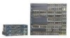
up to 2048 MAC addresses on the Catalyst 2924 XL, 2924C XL, and 2912 XL switches • Supports up to 8192 MAC addresses on the Catalyst 2924M XL, Catalyst 2924M XL DC and Catalyst 2912MF XL switches Figure 1-1 shows the switch models. Catalyst 2900 Series XL Hardware Installation Guide 1-2 78-6461-04 - Cisco 2960-48PST-L | Hardware Installation Guide - Page 23
300 WS-C2924-LRE-XL 4 fixed autosensing 10/100 ports 24 LRE ports INPUT OUTPUT PWR PWR RESET TEMP FAN 9X 10X 11X 12X Cisco RPS 300 WS-C2912-XL 12 fixed autosensing 10/100 ports MODE 1X 2X 3X 4X 5X 6X 7X 8X 9X 10X 10BaseT/100BASE-TX 11X 12X Catalyst 2900 SERIES XL WS-C2924C-XL - Cisco 2960-48PST-L | Hardware Installation Guide - Page 24
, and SNMP refer to the Catalyst 2900 Series XL and Catalyst 3500 Series XL Software Configuration Guide. Front-Panel Description Depending on the model, the switch front panels can have up to twenty-four 10/100 ports (See Figure 1-2), up to twelve 100BASE-FX ports (See Figure 1-3), two module slots - Cisco 2960-48PST-L | Hardware Installation Guide - Page 25
2900 SERIES XL 4 5 100BASE-FX 6 7 8 9 10 11 12 100BASE-FX ports Figure 1-4 Catalyst 2900 LRE XL 10/100 and LRE Ports INPUT OUTPUT PWR PWR RESET TEMP FAN 9X 10X 11X 12X 10/100 ports LRE ports Catalyst 2900 LRE XL 48005 78-6461-04 Catalyst 2900 Series XL Hardware Installation Guide - Cisco 2960-48PST-L | Hardware Installation Guide - Page 26
if the attached device supports it) and configures itself accordingly. The 10/100 ports on the Catalyst 2900 XL switches provide protocol support for Cisco IP Phones and per-port priority override. Refer to the Catalyst 2900 Series XL and Catalyst 3500 Series XL Software Configuration Guide for more - Cisco 2960-48PST-L | Hardware Installation Guide - Page 27
. For information about configuring the LRE ports, refer to the Catalyst 2900 Series XL and Catalyst 3500 Series XL Software Configuration Guide. For more information about the Cisco LRE CPE devices, refer to the Cisco LRE CPE Hardware Installation Guide. If telephone services, such as voice - Cisco 2960-48PST-L | Hardware Installation Guide - Page 28
other switch ports and is managed through the switch management interfaces. Table 1-1 lists the modules that the module slots support. Table 1-1 Expansion Modules Module Type 10/100 Ethernet 100 BASE-FX Model Number WS-X2914-XL WS-X2914-XL-V WS-X2922-XL WS-X2922-XL-V WS-X2924-XL-V Catalyst 2900 - Cisco 2960-48PST-L | Hardware Installation Guide - Page 29
Ethernet Gigabit module supports several Gigabit Interface Converter (GBIC) devices. For a complete list and the minimum software release required, refer to the Release Notes for the Catalyst 2900 Series XL and Catalyst 3500 Series XL Switches. These modules automatically configure themselves when - Cisco 2960-48PST-L | Hardware Installation Guide - Page 30
. The Catalyst 2900 Series XL and Catalyst 3500 Series XL Software Configuration Guide describes how to use CMS to manage standalone or individual switches and how to use cluster management software to manage switch clusters]. Figure 1-5 Catalyst 2912 XL, 2924 XL, and 2924C XL LEDs 10/100 port LEDs - Cisco 2960-48PST-L | Hardware Installation Guide - Page 31
1-6 Catalyst 2912MF XL, 2924M XL, and 2924M XL DC LEDs 10BASE-FX port LEDs Front-Panel Description 12 1 MODE 2 3 4 5 100BASE-FX 6 7 System LED RPS LED Expansion slot status LED Port mode LED Mode button 48003 78-6461-04 Catalyst 2900 Series XL Hardware Installation Guide 1-11 - Cisco 2960-48PST-L | Hardware Installation Guide - Page 32
operating normally. System is receiving power but is not functioning properly. For information on the System LED colors during POST, see the "Powering On the Switch and Running POST" section on page 2-24. 1-12 Catalyst 2900 Series XL Hardware Installation Guide 78-6461-04 - Cisco 2960-48PST-L | Hardware Installation Guide - Page 33
for redundant power system (RPS) descriptions specific for the switch. Table 1-2 and Table 1-3 list the RPS LED colors and their meanings. Figure 1-8 RPS LED on the Catalyst 2912 XL, 2924C XL, 2924 XL, 2924MF XL, 2924M XL, and 2924M XL DC Switches Color Off Green Blinking green Amber RPS - Cisco 2960-48PST-L | Hardware Installation Guide - Page 34
1-6 and Table 1-7 list the port LED colors. Table 1-4 Port Mode LEDs on the Catalyst 2912 XL, 2924C XL, 2924 XL, 2924MF XL, 2924M XL, and 2924M XL DC Switches Mode LED STAT UTL FDUP 100 Port Mode Port status Switch utilization Port duplex mode Port speed Description The port status. This is the - Cisco 2960-48PST-L | Hardware Installation Guide - Page 35
XL switches except the Catalyst 2912 LRE XL and Catalyst 2924 LRE XL switches. The port duplex mode: full duplex or half duplex. The default setting is half duplex. The port operating speed: 10 or 100 Mbps. The default setting is auto. 78-6461-04 Catalyst 2900 Series XL Hardware Installation Guide - Cisco 2960-48PST-L | Hardware Installation Guide - Page 36
Front-Panel Description Chapter 1 Product Overview Table 1-6 Meanings of Port Status LED Colors for Different Modes on Catalyst 2912 XL, 2924C XL, 2924 XL, 2924MF XL, 2924M XL, and 2924M XL DC Switches Port Mode STAT (port status) Port LED Color Off Solid green Flashing green Alternating green- - Cisco 2960-48PST-L | Hardware Installation Guide - Page 37
forwarding state. Cisco IOS Release 12.0(5.x)WC42 3 Cyan (off) Cyan (off) LRE port or remote CPE Ethernet port is operating in half-duplex mode. Green LRE port or remote CPE Ethernet port is operating in full-duplex mode. 78-6461-04 Catalyst 2900 Series XL Hardware Installation Guide 1-17 - Cisco 2960-48PST-L | Hardware Installation Guide - Page 38
port is operating at 100 Mbps. 1. The LEDs on Catalyst 2900 LRE XL switches with Cisco IOS Release 12.0(5.x)WC1 or Cisco IOS Release 12.0(5.x)WC2 provide information about the connected Cisco 575 LRE CPE devices. These IOS releases do not support the Cisco 585 LRE CPE devices. 2. The Catalyst 2900 - Cisco 2960-48PST-L | Hardware Installation Guide - Page 39
than the Catalyst 2924M XL DC switch, the rear panels of a Catalyst 2900 XL and Catalyst 2900 LRE XL switches have an AC power connector, an RPS connector, and an RJ-45 console port. (See Figure 1-10 through Figure 1-12.) Figure 1-10 Catalyst 2912 XL, 2924 XL, and 2924C XL Rear Panel Fans 47295 11 - Cisco 2960-48PST-L | Hardware Installation Guide - Page 40
the Catalyst 2924M XL DC switch has a DC power connector (also referred to as the terminal block header), an RJ-45 console port, and a ground lug. (See Figure 1-13.) The switch is shipped with a terminal block plug in the DC power connector. 1-20 Catalyst 2900 Series XL Hardware Installation Guide - Cisco 2960-48PST-L | Hardware Installation Guide - Page 41
Catalyst 2924M XL DC switch has an internal DC-power converter. It has dual feeds (A and B) that are diode-OR-ed into a single power block. For installation instructions, see the "Wiring the DC-Input Power Source" section on page 2-29. 78-6461-04 Catalyst 2900 Series XL Hardware Installation Guide - Cisco 2960-48PST-L | Hardware Installation Guide - Page 42
Cisco RPS models support specific Catalyst 2900 XL switches: • Cisco RPS 600 (model PWR600-AC-RPS)-supports the Catalyst 2912 XL, 2924C XL, 2924 XL, 2924MF XL, and 2924M XL switches. • Cisco RPS 300 (model PWR300-AC-RPS-N1)-supports the Catalyst 2912 LRE XL and 2924 LRE XL switches Note The Cisco - Cisco 2960-48PST-L | Hardware Installation Guide - Page 43
the switch console port to a terminal. You can order a kit (part number ACS-DSBUASYN=) containing that adapter from Cisco. For console port and adapter pinout information, see the "Connecting to the Console Port" section on page 2-42. 78-6461-04 Catalyst 2900 Series XL Hardware Installation Guide - Cisco 2960-48PST-L | Hardware Installation Guide - Page 44
Power Connectors Chapter 1 Product Overview 1-24 Catalyst 2900 Series XL Hardware Installation Guide 78-6461-04 - Cisco 2960-48PST-L | Hardware Installation Guide - Page 45
2 This chapter describes how to install your Catalyst 2900 XL switch and interpret the power-on self-test (POST Catalyst 2900 Series XL Modules Installation Guide and the Catalyst 2900 Series XL ATM Modules Installation and Configuration Guide for global information about the Catalyst 2900 series XL - Cisco 2960-48PST-L | Hardware Installation Guide - Page 46
or replace this equipment. Warning Read the installation instructions before you connect the system to its power as the main disconnecting device. Warning To prevent the switch from overheating, do not operate it in an area that Catalyst 2900 Series XL Hardware Installation Guide 2-2 78-6461-04 - Cisco 2960-48PST-L | Hardware Installation Guide - Page 47
with a power switch, line voltages are present within the power supply even when the power switch is off and the power cord is connected. For systems without a power switch, line voltages are all national laws and regulations. 78-6461-04 Catalyst 2900 Series XL Hardware Installation Guide 2-3 - Cisco 2960-48PST-L | Hardware Installation Guide - Page 48
matter of this manual. This is a Class A Information product. When used in a residential environment, it may cause radio frequency interference. Under such circumstances, the user may be requested to take appropriate countermeasures. Catalyst 2900 Series XL Hardware Installation Guide 2-4 78-6461 - Cisco 2960-48PST-L | Hardware Installation Guide - Page 49
this equipment is used in a domestic environment, radio disturbance may arise. When such trouble occurs, the user may be required to take corrective actions. 46464 Korea Warning This is be replaced with a residential-use type. 78-6461-04 Catalyst 2900 Series XL Hardware Installation Guide 2-5 - Cisco 2960-48PST-L | Hardware Installation Guide - Page 50
to 328 feet (100 meters). • For 100BASE-FX ports, cable lengths from the switch to connected devices are up to 1351 feet (412 meters) for half-duplex connections and less than 6561 feet (2 kilometers) for full-duplex connections. Catalyst 2900 Series XL Hardware Installation Guide 2-6 78-6461-04 - Cisco 2960-48PST-L | Hardware Installation Guide - Page 51
for support. Return all packing materials to the shipping container and save them. Your Catalyst 2900 XL switch is shipped with these items: • Where to Find the Catalyst 2900 XL and Catalyst 3500 XL Documentation flyer • Cisco Documentation CD-ROM • AC power cord 78-6461-04 Catalyst 2900 Series XL - Cisco 2960-48PST-L | Hardware Installation Guide - Page 52
brackets Note The cable guide does not attach to the Catalyst 2912 LRE XL and 2924 LRE XL switches. • One RJ-45-to-DB-9 adapter • Cisco Information Packet, containing warranty, safety, and support information Note In addition to these items, the Catalyst 2924M XL DC switch also ships with a DC - Cisco 2960-48PST-L | Hardware Installation Guide - Page 53
be attached to a 19-, 23-, or 24-inch rack. Figure 2-1 shows which mounting holes to use. Note Figure 2-1 shows brackets for two-rack-unit modular switches. Rack-mount points are similar on brackets for one-rack-unit switches. 78-6461-04 Catalyst 2900 Series XL Hardware Installation Guide 2-9 - Cisco 2960-48PST-L | Hardware Installation Guide - Page 54
the instructions described in these procedures: • "Removing Screws from the Switch" section on page 2-11 • "Attaching the Brackets to a Catalyst 2912 XL, 2924C XL, 2924 XL, 2912MF XL, 2924M XL, or 2924M XL DC Switch" section on page 2-11 2-10 Catalyst 2900 Series XL Hardware Installation Guide - Cisco 2960-48PST-L | Hardware Installation Guide - Page 55
Removing Screws from the Switch Catalyst 2900 SERIES XL Fixed-port Catalyst 2900 series XL Catalyst 2900 SERIES XL 22X 23X 24X Modular Catalyst 2900 series XL 47292 Attaching the Brackets to a Catalyst 2912 XL, 2924C XL, 2924 XL, 2912MF XL, 2924M XL, or 2924M XL DC Switch Follow these steps to - Cisco 2960-48PST-L | Hardware Installation Guide - Page 56
2912 XL, 2924C XL, and 2924 XL Fixed-Port Switches (Front-Panel Forward) Phillips flat-head screws Phillips truss-head screws 19" configuration MODE 1X 2X 3X 4X 5X 6X 7X 47738 23" and 24" configuration MODE 1X 2X 3X 4X 5X 6X 7X 2-12 Catalyst 2900 Series XL Hardware Installation Guide 78 - Cisco 2960-48PST-L | Hardware Installation Guide - Page 57
2924M XL, and 2924M XL DC Modular Switches (Front-Panel Forward) Phillips flat-head screws 19" configuration Phillips truss-head screws 12 MODE 1X 2X 3X 4X 5X 6X 7X 23" and 24" configuration 12 MODE 1X 2X 3X 4X 5X 6X 7X 47297 78-6461-04 Catalyst 2900 Series XL Hardware Installation Guide - Cisco 2960-48PST-L | Hardware Installation Guide - Page 58
Figure 2-6 Attaching Brackets on Catalyst 2912 XL, 2924C XL, and 2924 XL Fixed-Port Switches (Rear-Panel Forward) 19" configuration Phillips flat-head screws 23" and 24" configuration Phillips truss-head screws 47298 2-14 Catalyst 2900 Series XL Hardware Installation Guide 78-6461-04 - Cisco 2960-48PST-L | Hardware Installation Guide - Page 59
" configuration Figure 2-8 Attaching Brackets for Telco Racks 47299 DC INPUT 21.00A0-/11R2.0A0AT/2IN050G0--26400HVZ~ Phillips flat-head screws 71236 Note Only the Catalyst 2912MF XL, Catalyst 2924M XL, and Catalyst 2924M XL DC switches can be mounted in telco racks. 78-6461-04 Catalyst 2900 - Cisco 2960-48PST-L | Hardware Installation Guide - Page 60
to a Catalyst 2912 LRE XL or 2924 LRE XL switch, use the supplied Phillips flat-head screws to attach the long side of the bracket to the switch. Note Do not install an LRE switch in a 23- or 24-inch rack. The mounting brackets shipped with a Catalyst 2900 LRE XL switch cannot support the switch in - Cisco 2960-48PST-L | Hardware Installation Guide - Page 61
and 2924 LRE XL Switches (Front-Panel Forward) Phillips flat-head screws Phillips truss-head screws 19" configuration INPUT OUTPUT PWR PWR RESET TEMP FAN 9X 10X 11X 12X 23" and 24" configuration INPUT OUTPUT PWR PWR RESET TEMP FAN 9X 10X 11X 12X 54728 78-6461-04 Catalyst 2900 Series XL - Cisco 2960-48PST-L | Hardware Installation Guide - Page 62
23" and 24" configuration Mounting the Switch in a Rack After the brackets are attached to the switch, use the four supplied number-12 Phillips machine screws to securely attach the brackets to the rack, as shown in Figure 2-11. 2-18 Catalyst 2900 Series XL Hardware Installation Guide 78-6461-04 - Cisco 2960-48PST-L | Hardware Installation Guide - Page 63
1X 2X 3X Catalyst 2900 SERIES XL 4X 5X 6X 7X 8X 9X 100BaseFX 10X 11X 12X 13X 14X 15X 16X 17X 18X 19X 20X 21X 22X 23X 24X Phillips machine screws After the switch is mounted in the rack, power the switch as described in "Powering On the Switch and Running POST" section on page - Cisco 2960-48PST-L | Hardware Installation Guide - Page 64
does not attach to the Catalyst 2912 LRE XL and 2924 LRE XL switches. Figure 2-12 Attaching the Cable Guide MODE 1X 2X 3X 4X 5X 6X 7X 8X 9X 10X 10BaseT/100Ba1s0e0TBXaseFX 11X 12X 13X 14X Cable guide screw 16X 17X 18X 19X 20X 21X Catalyst 2900 SERIES XL 22X 23X 24X 47302 12 - Cisco 2960-48PST-L | Hardware Installation Guide - Page 65
the switch. Follow the same steps to attach the second bracket to the opposite side of the switch. Figure 2-13 Attaching Brackets for Parallel and Vertical Wall-Mounting for Fixed-Port Switches 78-6461-04 47303 Phillips truss-head screws Catalyst 2900 Series XL Hardware Installation Guide 2-21 - Cisco 2960-48PST-L | Hardware Installation Guide - Page 66
Mounting the Switch to a Wall For best support of the switch and cables, make sure the switch is attached securely to a wall stud or to a firmly attached plywood mounting backboard, as shown in Figure 2-15, Figure 2-16, and Figure 2-28. 2-22 Catalyst 2900 Series XL Hardware Installation Guide 78 - Cisco 2960-48PST-L | Hardware Installation Guide - Page 67
a Fixed-Port Switch to a Wall Vertical wall stud SERIES 24x 23x User-supplied screws 22x 21x 20x 19x 18x 17x 16x 15x 14x 13x 10BaseT/100BaseTx 12x 11x 10x 9x 8x 7x 6x 5x 4x 3x 2x 1x 47305 RPS MODE 78-6461-04 Catalyst 2900 Series XL Hardware Installation Guide 2-23 - Cisco 2960-48PST-L | Hardware Installation Guide - Page 68
2-24 As the switch powers on, it begins POST, a series of eight tests that run automatically to ensure that the switch functions properly. When the switch begins POST, the port LEDs turn amber for 2 seconds, and then they turn green. Catalyst 2900 Series XL Hardware Installation Guide 78-6461-04 - Cisco 2960-48PST-L | Hardware Installation Guide - Page 69
3, "Troubleshooting," to determine a course of action. POST failures are usually fatal. Call Cisco Systems immediately if your switch does not pass POST. Connecting to DC Power To connect the Catalyst 2924M XL DC switch to a DC-input power source, follow the steps in these sections: • Preparing - Cisco 2960-48PST-L | Hardware Installation Guide - Page 70
Wire-stripping tool(s) for stripping both 6- and 12- or 14-gauge wires Grounding the Switch Warning This equipment is intended to be grounded. Ensure that the host is connected to rear panel of the switch. (See Figure 2-17. 2-26 Catalyst 2900 Series XL Hardware Installation Guide 78-6461-04 - Cisco 2960-48PST-L | Hardware Installation Guide - Page 71
the exposed area of the 6-gauge wire. Using a Panduit crimping tool, crimp the ground lug to the 6-gauge wire. (See Figure 2-19.) 78-6461-04 Catalyst 2900 Series XL Hardware Installation Guide 2-27 - Cisco 2960-48PST-L | Hardware Installation Guide - Page 72
16 screws to attach the ground lug and wire assembly to the rear panel of the switch. Using a ratcheting torque screwdriver, torque each ground-lug screw to 15 1bf-in. (or 240 ounce-force inches [240 ozf-in.]). (See Figure 2-20.) 2-28 Catalyst 2900 Series XL Hardware Installation Guide 78-6461-04 - Cisco 2960-48PST-L | Hardware Installation Guide - Page 73
. To ensure that all power is OFF, locate the circuit breaker on the panel board that services the DC circuit, switch the circuit breaker to the OFF position, and tape the switch handle of the circuit breaker in the OFF position. 78-6461-04 Catalyst 2900 Series XL Hardware Installation Guide 2-29 - Cisco 2960-48PST-L | Hardware Installation Guide - Page 74
.) The wiring sequence is return to return and negative to negative for both the A feed wires and the B feed wires. The rear panel of the switch identifies the positive and negative positions for both the A and B feed wires. 2-30 Catalyst 2900 Series XL Hardware Installation Guide 78-6461-04 - Cisco 2960-48PST-L | Hardware Installation Guide - Page 75
Chapter 2 Installation Figure 2-22 Positive and Negative Positions on the Switch Rear Panel Connecting to DC Power 74078 CONSOLE BERFEOFREERPOCTOWONEMNRAENCUTAINL G DC INPUT ICNUPRURTE: 3N6T:- 72 the terminal block plug. 78-6461-04 Catalyst 2900 Series XL Hardware Installation Guide 2-31 - Cisco 2960-48PST-L | Hardware Installation Guide - Page 76
ozf-in.). (See Figure 2-25.) Caution Do not overtorque the terminal-block captive screws. The recommended maximum torque is 4.5 lbf-in. (72 ozf-in.). 2-32 Catalyst 2900 Series XL Hardware Installation Guide 78-6461-04 - Cisco 2960-48PST-L | Hardware Installation Guide - Page 77
6 Repeat Steps 4 and 5 for the remaining three DC-input power source wires. Figure 2-26 shows the completed wiring of a terminal block plug. 78-6461-04 Catalyst 2900 Series XL Hardware Installation Guide 2-33 - Cisco 2960-48PST-L | Hardware Installation Guide - Page 78
header on the rear panel of the switch. (See Figure 2-27.) Caution Secure the wires coming from the terminal block so that they will not be disturbed by casual contact. For example, use tie wraps to secure the wires to a rack. 2-34 Catalyst 2900 Series XL Hardware Installation Guide 78-6461-04 - Cisco 2960-48PST-L | Hardware Installation Guide - Page 79
an RJ-45 connector on the front panel (Figure 2-28). When connecting to switches or repeaters, use a crossover Category 5 cable. Pinouts for the cables are described in the "Cable and Adapter Specifications" section on page B-4. 78-6461-04 Catalyst 2900 Series XL Hardware Installation Guide 2-35 - Cisco 2960-48PST-L | Hardware Installation Guide - Page 80
to the switch. Refer to the documentation that came with your Cisco IP Troubleshooting," for solutions to cabling problems. Reconfigure and reboot the connected device if necessary. Repeat Steps 1 through 3 to connect to each 10/100 port. 2-36 Catalyst 2900 Series XL Hardware Installation Guide - Cisco 2960-48PST-L | Hardware Installation Guide - Page 81
, follow these steps: Step 1 Step 2 Remove the rubber plugs from the port and the rubber caps from the cable connectors. Connect one end of the fiber-optic cable to the 100BASE-FX port on the switch, as shown in Figure 2-29. 78-6461-04 Catalyst 2900 Series XL Hardware Installation Guide 2-37 - Cisco 2960-48PST-L | Hardware Installation Guide - Page 82
through a patch panel. Note You can connect both Cisco 575 LRE CPE and Cisco 585 LRE CPE devices to your LRE switch, and you can hot swap the CPE devices without powering down the switch or disrupting the other switch ports. 2-38 Catalyst 2900 Series XL Hardware Installation Guide 78-6461-04 - Cisco 2960-48PST-L | Hardware Installation Guide - Page 83
your Cisco sales representative for more information. To connect the LRE port to a patch panel or POTS splitter, follow these steps: Step 1 Connect one end of a wiring trunk cable to the RJ-21 connector of the LRE port on the switch. (See Figure 2-30.) 78-6461-04 Catalyst 2900 Series XL Hardware - Cisco 2960-48PST-L | Hardware Installation Guide - Page 84
Connecting to an LRE Port Figure 2-30 Connecting to an LRE Port Screw SYSTEM RPS MODE LRE STAT DUPLX SPEED 1X 2X 3X 4X Screw Cable connector 54560 Screw RJ-21 connector Cable to wiring trunk 0.20 inch (5 mm) Cable tie 2-40 Catalyst 2900 Series XL Hardware Installation Guide 78-6461-04 - Cisco 2960-48PST-L | Hardware Installation Guide - Page 85
about the LRE link between the switch LRE port and the CPE, as well as information about the configuration and management of CPE devices, refer to the Catalyst 2900 Series XL and Catalyst 3500 Series XL Software Configuration Guide. For more information about the Cisco LRE CPE devices, refer to the - Cisco 2960-48PST-L | Hardware Installation Guide - Page 86
• 1 stop bit • No parity After you have accessed the switch, you can change the port baud rate to its original setting. See the Catalyst 2900 Series XL and Catalyst 3500 Series XL Software Configuration Guide for instructions. 2-42 Catalyst 2900 Series XL Hardware Installation Guide 78-6461-04 - Cisco 2960-48PST-L | Hardware Installation Guide - Page 87
the Catalyst 2900 Series XL and Catalyst 3500 Series XL Cisco IOS Release 12.0(5)WC(1). For information about configuring the switch, refer to the Catalyst 2900 Series XL and Catalyst 3500 Series XL Software Configuration Guide. 78-6461-04 Catalyst 2900 Series XL Hardware Installation Guide 2-43 - Cisco 2960-48PST-L | Hardware Installation Guide - Page 88
Where to Go Next Chapter 2 Installation 2-44 Catalyst 2900 Series XL Hardware Installation Guide 78-6461-04 - Cisco 2960-48PST-L | Hardware Installation Guide - Page 89
See the Catalyst 2900 Series XL and Catalyst 3500 Series XL Software Configuration Guide, the Catalyst 2900 Series XL and Catalyst 3500 Series XL Command Reference, or the documentation that came with your SNMP application for details. This chapter describes these topics for troubleshooting problems - Cisco 2960-48PST-L | Hardware Installation Guide - Page 90
Module POST Failures If you install modules WS-X2914-XL or WS-X2922-XL in a Catalyst 2924M XL or Catalyst 2912MF XL switch, the module fails POST. This failure occurs because the expansion modules support 2048 MAC addresses and the switch supports 8192 MAC addresses. To correct the failure - Cisco 2960-48PST-L | Hardware Installation Guide - Page 91
Chapter 3 Troubleshooting Diagnosing Problems Diagnosing Problems Common switch problems fall into the following categories: • Poor performance • No connectivity • Corrupted software Table 3-2 describes how to detect and resolve these problems. 78-6461-04 Catalyst 2900 Series XL Hardware - Cisco 2960-48PST-L | Hardware Installation Guide - Page 92
Diagnosing Problems Chapter 3 Troubleshooting Table 3-2 Common Problems and Their Solutions Symptom Poor Performance or Excessive Errors. Possible Cause Resolution Duplex autonegotiation mismatch. Refer to the Catalyst 2900 Series XL and Catalyst 3500 Series XL Software Configuration Guide - Cisco 2960-48PST-L | Hardware Installation Guide - Page 93
. Repair cable trunking or select an alternative pair. Cisco LRE CPE not communicating with or might be attempting to exceed rate or reach selected by the Catalyst 2900 LRE XL switch. Verify switch and upstream network status. 78-6461-04 Catalyst 2900 Series XL Hardware Installation Guide 3-5 - Cisco 2960-48PST-L | Hardware Installation Guide - Page 94
Diagnosing Problems Chapter 3 Troubleshooting Table 3-2 Common Problems and Their Solutions (continued) device, and refer to installation guide. Consider modification to topology to shorten reach or improve wiring quality. Catalyst 2900 Series XL Hardware Installation Guide 3-6 78-6461-04 - Cisco 2960-48PST-L | Hardware Installation Guide - Page 95
too poor to support desired profile. • Change to a lower profile. For more information, refer to the Catalyst 2900 Series XL and Catalyst 3500 Series XL Software Configuration Guide. • Assess possibility of improving trunk quality. Excessive interference from other services in bundle. • Consider - Cisco 2960-48PST-L | Hardware Installation Guide - Page 96
Diagnosing Problems Chapter 3 Troubleshooting Table 3-2 Common Problems and Their Solutions (continued) Symptom Possible Cause microfilters. For more information about microfilters, contact your Cisco sales representative. Catalyst 2900 Series XL Hardware Installation Guide 3-8 78-6461-04 - Cisco 2960-48PST-L | Hardware Installation Guide - Page 97
Chapter 3 Troubleshooting Diagnosing Problems Table 3-2 Common Problems and Their Solutions (continued) Symptom Ethernet more information, refer to the Catalyst 2900 Series XL and Catalyst 3500 Series XL Software Configuration Guide. 78-6461-04 Catalyst 2900 Series XL Hardware Installation - Cisco 2960-48PST-L | Hardware Installation Guide - Page 98
Diagnosing Problems Chapter 3 Troubleshooting 3-10 Catalyst 2900 Series XL Hardware Installation Guide 78-6461-04 - Cisco 2960-48PST-L | Hardware Installation Guide - Page 99
Table A-5 list the technical specifications for the Catalyst 2900 series switches. For switches that support modules (Catalyst 2912MF XL and 2924M XL), also refer to the Catalyst 2900 Series XL Modules Installation Guide and the Catalyst 2900 Series XL ATM Modules Installation Guide for additional - Cisco 2960-48PST-L | Hardware Installation Guide - Page 100
Specifications Table A-1 Technical Specifications for the Catalyst 2912 XL and Catalyst 2912MF XL Switches Environmental Ranges Operating temperature Storage temperature Operating humidity Operating altitude Storage altitude Power Requirements AC input voltage DC input voltages Catalyst 2912 XL - Cisco 2960-48PST-L | Hardware Installation Guide - Page 101
Appendix A Technical Specifications Table A-2 Technical Specifications for the Catalyst 2924 XL and Catalyst 2924C XL Switches Catalyst 2924 XL Environmental Operating Ranges Operating nm1 -14 dBm2 -19 to -14 dBm -19 to -14 dBm 78-6461-04 Catalyst 2900 Series XL Hardware Installation Guide A-3 - Cisco 2960-48PST-L | Hardware Installation Guide - Page 102
Appendix A Technical Specifications Table A-3 Technical Specifications for the Catalyst 2924M XL Switches Environmental Operating Ranges Operating temperature 32 to 113°F (0 (H x W x D) 3.46 x 17.5 x 12 in. (8.8 x 44.5 x 30.5 cm) Catalyst 2900 Series XL Hardware Installation Guide A-4 78-6461-04 - Cisco 2960-48PST-L | Hardware Installation Guide - Page 103
Technical Specifications for Catalyst 2924M XL DC Switches Environmental cm) Table A-5 Technical Specifications for the Catalyst 2912 LRE XL and 2924 LRE XL Switches Environmental Operating Ranges Operating temperature 15,000 ft (4570 m) Catalyst 2900 Series XL Hardware Installation Guide A-5 - Cisco 2960-48PST-L | Hardware Installation Guide - Page 104
EMI FCC Part 15 Class A EN 55022 Class A (CISPR 22 Class A) VCCI Class A AS/NZS 3548 Class A BCIQ CE Table A-7 Agency Approvals (Catalyst 2924M XL DC Switch) Safety NOM 019 BSMI EMC EN 50082-1 Class A BSMI NEBS GR-1089 GR-63 Catalyst 2900 Series XL Hardware Installation Guide A-6 78-6461-04 - Cisco 2960-48PST-L | Hardware Installation Guide - Page 105
APPENDIX B Connectors and Cable Specifications This appendix describes the Catalyst 2900 XL switch ports and the cables and adapters that you use to connect the switch to other devices. Connector Specifications 10/100 Ports The 10/100 Ethernet ports use standard RJ-45 connectors and Ethernet - Cisco 2960-48PST-L | Hardware Installation Guide - Page 106
and cables are designated with an X or when both ports do not have an X. 100BASE-FX Ports 100BASE-FX ports use duplex SC connectors, as shown in Figure B-2. These ports use 10/125- or 62.5/125-micron multimode fiber-optic cabling. Catalyst 2900 Series XL Hardware Installation Guide B-2 78-6461-04 - Cisco 2960-48PST-L | Hardware Installation Guide - Page 107
B-4. The supplied RJ-45-to-RJ-45 rollover cable and DB-9 adapter are used to connect the console port of the switch to a console PC. You need to provide a RJ-45-to-DB-25 female DTE adapter if you want to connect the switch console 78-6461-04 Catalyst 2900 Series XL Hardware Installation Guide B-3 - Cisco 2960-48PST-L | Hardware Installation Guide - Page 108
in Figure B-4 and Figure B-5. Figure B-4 Crossover Cable Schematic Switch 3 TD+ 6 TD- Switch 3 TD+ 6 TD- 1 RD+ 2 RD- 1 RD+ 2 RD- H5579 Figure B-5 Straight-Through Cable Schematic Switch 3 TD+ 6 TD- Router or PC 3 RD+ 6 RD Catalyst 2900 Series XL Hardware Installation Guide B-4 78-6461-04 - Cisco 2960-48PST-L | Hardware Installation Guide - Page 109
in Table B-2. The supplied RJ-45-to-RJ-45 rollover cable and adapters connect the console port of the switch to a console PC or terminal. The following sections describe the rollover cable and adapters for the console port. 78-6461-04 Catalyst 2900 Series XL Hardware Installation Guide B-5 - Cisco 2960-48PST-L | Hardware Installation Guide - Page 110
Rollover Cable Appendix B Connectors and Cable Specifications Identifying a Rollover Cable You can identify Console Port to a PC Catalyst 2900 series XL RJ-45-to-RJ-45 PC rollover cable RJ-45-to-DB-9 adapter (labeled TERMINAL) H10972 Catalyst 2900 Series XL Hardware Installation Guide B-6 - Cisco 2960-48PST-L | Hardware Installation Guide - Page 111
console port, the RJ-45-to-RJ-45 rollover cable, and the RJ-45-to-DB-25 female DTE adapter. Note The RJ-45-to-DB-25 female DTE adapter is not supplied with the switch. You can order a kit (part number ACS-DSBUASYN=) containing this adapter from Cisco. 78-6461-04 Catalyst 2900 Series XL - Cisco 2960-48PST-L | Hardware Installation Guide - Page 112
Appendix B Connectors and Cable Specifications Table B-3 Console Port Signaling and Cabling Using a DB-25 Adapter Console Port (DTE) Signal RTS Not connected 3 7 7 2 20 4 Console Device Signal CTS DSR RxD GND GND TxD DTR RTS Catalyst 2900 Series XL Hardware Installation Guide B-8 78-6461-04 - Cisco 2960-48PST-L | Hardware Installation Guide - Page 113
translated warnings can be used with other documents related to this guide. Attaching the Cisco RPS (model PWR600-AC-RPS) This warning applies to the Catalyst 2912 XL, 2924 XL, 2924C XL, 2924M XL, and 2924C XL switches. Warning Attach only the Cisco RPS (model PWR600-AC-RPS) to the RPS receptacle - Cisco 2960-48PST-L | Hardware Installation Guide - Page 114
-AC-RPS) al receptáculo RPS. Varning! Koppla endast Ciscos RPS (modell PWR600-AC-RPS) till RPS-uttaget. Attaching the Cisco RPS (model PWR300-AC-RPS-N1) This warning applies to the Catalyst 2912 LRE XL and 2924 LRE XL switches. Warning Attach only the Cisco RPS (model PWR300-AC-RPS-N1) to the RPS - Cisco 2960-48PST-L | Hardware Installation Guide - Page 115
Ciscos RPS (modell PWR300-AC-RPS-N1) till RPS-uttaget. Qualified Personnel Warning Warning Only trained and qualified personnel should be allowed to install or replace this equipment Waarschuwing Installatie en e qualificado. 78-6461-04 Catalyst 2900 Series XL Hardware Installation Guide C-3 - Cisco 2960-48PST-L | Hardware Installation Guide - Page 116
av utbildad och kvalificerad personal. Installation Warning Warning Read the installation instructions before you connect the system to its power source. Waarschuwing Raadpleeg ção antes de ligar o sistema à sua fonte de energia. Catalyst 2900 Series XL Hardware Installation Guide C-4 78-6461-04 - Cisco 2960-48PST-L | Hardware Installation Guide - Page 117
inclusief ringen, kettingen en horloges) verwijderen. Metalen voorwerpen worden warm wanneer ze met stroom en aarde zijn verbonden, en kunnen ernstige brandwonden des blessures graves ou souder l'objet métallique aux bornes. 78-6461-04 Catalyst 2900 Series XL Hardware Installation Guide C-5 - Cisco 2960-48PST-L | Hardware Installation Guide - Page 118
är kopplad till kraftledningar. Metallobjekt hettas upp när de kopplas ihop med ström och jord och kan förorsaka allvarliga brännskador; metallobjekt kan också sammansvetsas med kontakterna. Catalyst 2900 Series XL Hardware Installation Guide C-6 78-6461-04 - Cisco 2960-48PST-L | Hardware Installation Guide - Page 119
. Avertissement Ne placez pas ce châssis sur un autre appareil. En cas de chute, il pourrait provoquer de graves blessures corporelles et d'importants dommages allvarlig kroppsskada såväl som skada på utrustningen uppstå. 78-6461-04 Catalyst 2900 Series XL Hardware Installation Guide C-7 - Cisco 2960-48PST-L | Hardware Installation Guide - Page 120
as the main disconnecting device. Waarschuwing De combinatie van de stekker en het elektrisch contactpunt moet te allen tijde toegankelijk zijn omdat deze , eftersom denna koppling utgör den huvudsakliga frånkopplingsanordningen. Catalyst 2900 Series XL Hardware Installation Guide C-8 78-6461-04 - Cisco 2960-48PST-L | Hardware Installation Guide - Page 121
C Translated Safety Warnings Overtemperature Warning Overtemperature Warning Warning To prevent the switch from overheating, do not operate it in an area that exceeds the libero di 7,6 cm intorno alle aperture di ventilazione. 78-6461-04 Catalyst 2900 Series XL Hardware Installation Guide C-9 - Cisco 2960-48PST-L | Hardware Installation Guide - Page 122
de ventilação. ¡Advertencia! Para evitar que el interruptor se recaliente, no se debe usar en áreas cuya temperatura ambiente exceda la máxima recomendada, esto es, 40°C (104°F). die Verwendung mit TN-Stromsystemen ausgelegt. C-10 Catalyst 2900 Series XL Hardware Installation Guide 78-6461-04 - Cisco 2960-48PST-L | Hardware Installation Guide - Page 123
l'appareil, la mise à la terre doit toujours être connectée en premier et déconnectée en dernier. Warnung Der Erdanschluß muß bei der Installation der Einheit , må jordledningen alltid tilkobles først og frakobles sist. 78-6461-04 Catalyst 2900 Series XL Hardware Installation Guide C-11 - Cisco 2960-48PST-L | Hardware Installation Guide - Page 124
fusible ou qu'un disjoncteur de 120 V alt., 15 A U.S. maximum (240 V alt., 16 A international) est utilisé sur les conducteurs de phase (conducteurs de charge). C-12 Catalyst 2900 Series XL Hardware Installation Guide 78-6461-04 - Cisco 2960-48PST-L | Hardware Installation Guide - Page 125
produktet er avhengig av bygningens installasjoner av kortslutningsbeskyttelse (overstrøm). Kontroller at det brukes en sikring eller strømbryter som ikke er større enn 120 VAC, 15 öm, 16 A (i USA max. 120 V växelström, 15 A). 78-6461-04 Catalyst 2900 Series XL Hardware Installation Guide C-13 - Cisco 2960-48PST-L | Hardware Installation Guide - Page 126
equipo principal esté conectado a tierra durante el uso normal. Varning! Denna utrustning är avsedd att jordas. Se till att värdenheten är jordad vid normal användning. C-14 Catalyst 2900 Series XL Hardware Installation Guide 78-6461-04 - Cisco 2960-48PST-L | Hardware Installation Guide - Page 127
au circuit d'alimentation afin de ne pas surcharger les connections. Achtung Beim Anschließen der Geräte an das Stromnetz ist darauf zu achten, daß die de fornecimento de energia, para não sobrecarregar a instalação. 78-6461-04 Catalyst 2900 Series XL Hardware Installation Guide C-15 - Cisco 2960-48PST-L | Hardware Installation Guide - Page 128
indiquée sur l'étiquette est différente de la tension de l'alimentation, ne connectez en aucun cas le châssis à la prise. Achtung Bei nicht übereinstimmender Spannung kann es zu , non collegare lo chassis a tale presa. C-16 Catalyst 2900 Series XL Hardware Installation Guide 78-6461-04 - Cisco 2960-48PST-L | Hardware Installation Guide - Page 129
in de voeding, zelfs wanneer de stroomschakelaar uitgeschakeld is en het netsnoer aangesloten is. Bij systemen zonder een stroomschakelaar zijn er lijnspanningen aanwezig in de voeding wanneer het netsnoer aangesloten is. 78-6461-04 Catalyst 2900 Series XL Hardware Installation Guide C-17 - Cisco 2960-48PST-L | Hardware Installation Guide - Page 130
'interno dell'alimentatore anche quando l'interruttore di alimentazione è en posizione di disattivazione (off), se il cavo dell'alimentazione uten en strømbryter, er det spenning i strømforsyningsenheten når strømledingen er tilkoblet. C-18 Catalyst 2900 Series XL Hardware Installation Guide 78 - Cisco 2960-48PST-L | Hardware Installation Guide - Page 131
ligado. ¡Advertencia! No tocar la fuente de alimentación mientras el cable esté enchufado. En sistemas con interruptor de alimentación, hay voltajes de línea dentro de la fuente, incluso kabels aan te sluiten of te ontkoppelen. 78-6461-04 Catalyst 2900 Series XL Hardware Installation Guide C-19 - Cisco 2960-48PST-L | Hardware Installation Guide - Page 132
pendant un orage. Warnung Arbeiten Sie nicht am System und schließen Sie keine Kabel an bzw. trennen Sie keine ab, wenn en la atmósfera. Varning! Vid åska skall du aldrig utföra arbete på systemet eller ansluta eller koppla loss kablar. C-20 Catalyst 2900 Series XL Hardware Installation Guide - Cisco 2960-48PST-L | Hardware Installation Guide - Page 133
van dit product dient te geschieden in overeenstemming met alle nationale wetten en reglementen. Varoitus Tämä tuote on hävitettävä kansallisten lakien ja määräysten mukaisesti produkten enligt gällande lagar och bestämmelser. 78-6461-04 Catalyst 2900 Series XL Hardware Installation Guide C-21 - Cisco 2960-48PST-L | Hardware Installation Guide - Page 134
geöffneten Ausgänge ist zu vermeiden. Avvertenza. Delle aperture delle porte del modulo apparato supervisore monomodale 100BASE-FX possono essere emesse radiazioni laser radiação e não fixe o seu olhar nos orifícios abertos. C-22 Catalyst 2900 Series XL Hardware Installation Guide 78-6461-04 - Cisco 2960-48PST-L | Hardware Installation Guide - Page 135
utsatt for strålen. Aviso Evite exposição ao raio. ¡Advertencia! Evitar la exposición al haz. Varning! Utsätt dig inte för laserstrålningen. 78-6461-04 Catalyst 2900 Series XL Hardware Installation Guide C-23 - Cisco 2960-48PST-L | Hardware Installation Guide - Page 136
on a system that does not have an on/off switch. Waarschuwing Voordat u aan een systeem werkt dat geen aan Før det skal utføres arbeid på et system som ikke har en av/på-bryter, skal strømledningen trekkes ut. Aviso Antes de começ Catalyst 2900 Series XL Hardware Installation Guide 78-6461-04 - Cisco 2960-48PST-L | Hardware Installation Guide - Page 137
. • If the rack is provided with stabilizing devices, install the stabilizers before mounting or servicing the unit in the rack. Om lichamelijk letsel te voorkomen wanneer u dit toestel in een of het daar een servicebeurt geeft. 78-6461-04 Catalyst 2900 Series XL Hardware Installation Guide C-25 - Cisco 2960-48PST-L | Hardware Installation Guide - Page 138
Warning-Rack-Mounting and Servicing Chapter C Translated Safety unité est montée dans un casier partiellement rempli, charger le casier de bas en haut en plaçant l'élément le plus lourd dans le bas. • Si le casier est warten. C-26 Catalyst 2900 Series XL Hardware Installation Guide 78-6461-04 - Cisco 2960-48PST-L | Hardware Installation Guide - Page 139
Chapter C Translated Safety Warnings Chassis Warning-Rack-Mounting and Servicing Avvertenza Per evitare infortuni fisici durante il montaggio o la før montering eller utføring av reparasjonsarbeid på enheten i kabinettet. 78-6461-04 Catalyst 2900 Series XL Hardware Installation Guide C-27 - Cisco 2960-48PST-L | Hardware Installation Guide - Page 140
Rack-Mounting and Servicing Chapter C llningen skall den installeras längst ned på ställningen. • Om denna enhet installeras på en delvis fylld ställning skall ställningen fyllas nedifrån och upp, med de tyngsta på ställningen. C-28 Catalyst 2900 Series XL Hardware Installation Guide 78-6461-04 - Cisco 2960-48PST-L | Hardware Installation Guide - Page 141
klant dient versterkte isolatie tussen de primaire wisselstroom en de 48 VDC-uitgang te verschaffen. Varoitus volts du client doit assurer une isolation renforcée entre l'alimentation CA principale et la sortie 48 V CC. Warnung Das 48 04 Catalyst 2900 Series XL Hardware Installation Guide C-29 - Cisco 2960-48PST-L | Hardware Installation Guide - Page 142
Warnung Der Catalyst 2924M XL DC-Switch ist ausschlie Catalyst 2924M XL DC ha sido diseñado para su uso exclusivo con conexiones WAN (Redes de área amplia). Esta unidad no ha recibido certificación para su uso en redes telefónicas públicas. C-30 Catalyst 2900 Series XL Hardware Installation Guide - Cisco 2960-48PST-L | Hardware Installation Guide - Page 143
The Catalyst 2924M XL DC switch contains no field-replaceable units (FRUs). Do not open the chassis or attempt to remove or replace any components. For information about obtaining service for this unit, contact your reseller or Cisco sales representative. Waarschuwing De Catalyst 2924M XL DC - Cisco 2960-48PST-L | Hardware Installation Guide - Page 144
om service av enheten. Installation Warning Warning Read the installation instructions before you connect the system to its power source. Waarschuwing Raadpleeg de installatie-aanwijzingen voordat u het systeem met de voeding verbindt. C-32 Catalyst 2900 Series XL Hardware Installation Guide 78 - Cisco 2960-48PST-L | Hardware Installation Guide - Page 145
Sie die Installationsanweisungen, bevor Sie das System an die Stromquelle anschließen. Avvertenza Consultare le istruzioni di installazione prima di collegare il sistema aan op een enkele bron met extra-lage spanning (SELV). 78-6461-04 Catalyst 2900 Series XL Hardware Installation Guide C-33 - Cisco 2960-48PST-L | Hardware Installation Guide - Page 146
fuente de voltaje extra-bajo (SELV, extra-low voltage source). Varning! Anslut utrustningen till en enstaka, SELV (skyddskrets för mycket låg spänning) strömförsörjningskälla. installé uniquement dans une zone à accès limité. C-34 Catalyst 2900 Series XL Hardware Installation Guide 78-6461-04 - Cisco 2960-48PST-L | Hardware Installation Guide - Page 147
para ser instalado numa área de acesso restrito. ¡Advertencia! El equipo debe instalarse en una zona de acceso restringido. Varning! Utrustningen måste installeras på plats med åtkomst in un ambiente di ufficio centrale. 78-6461-04 Catalyst 2900 Series XL Hardware Installation Guide C-35 - Cisco 2960-48PST-L | Hardware Installation Guide - Page 148
sia collegato alla massa di terra durante il normale utilizzo. Advarsel Dette utstyret skal jordes. Forviss deg om vertsterminalen er jordet ved normalt bruk. C-36 Catalyst 2900 Series XL Hardware Installation Guide 78-6461-04 - Cisco 2960-48PST-L | Hardware Installation Guide - Page 149
de l'appareil, la mise à la terre doit toujours être connectée en premier et déconnectée en dernier. Warnung Der Erdanschluß muß bei der Installation der Einheit immer primo il collegamento a massa e disconnetterlo per ultimo. 78-6461-04 Catalyst 2900 Series XL Hardware Installation Guide C-37 - Cisco 2960-48PST-L | Hardware Installation Guide - Page 150
to install or replace this equipment Waarschuwing Installatie en reparaties mogen uitsluitend door getraind en bevoegd personeel uitgevoerd worden. Varoitus Ainoastaan koulutettu æring bør montere eller bytte ut dette utstyret. C-38 Catalyst 2900 Series XL Hardware Installation Guide 78-6461-04 - Cisco 2960-48PST-L | Hardware Installation Guide - Page 151
panel board that services the DC circuit, switch the circuit breaker to the OFF position, and tape the switch handle of the circuit draait de stroomverbreker naar de UIT positie en plakt de schakelaarhendel van de stroomverbreker met plakband Catalyst 2900 Series XL Hardware Installation Guide C-39 - Cisco 2960-48PST-L | Hardware Installation Guide - Page 152
en courant continu n'est plus sous tension. Pour en être sûr, localiser le disjoncteur situé sur le panneau de service du circuit en courant continu, placer le disjoncteur en position interruptor do disjuntor com fita isoladora. C-40 Catalyst 2900 Series XL Hardware Installation Guide 78-6461-04 - Cisco 2960-48PST-L | Hardware Installation Guide - Page 153
a la posición de Apagado (OFF), y sujetar con cinta la palanca del interruptor automático en posición de Apagado (OFF). Varning! Innan du utför någon av följande procedurer måste du ître hors du bloc d'alimentation du terminal. 78-6461-04 Catalyst 2900 Series XL Hardware Installation Guide C-41 - Cisco 2960-48PST-L | Hardware Installation Guide - Page 154
. Varning! En blottad trådledning från en likströmsförsörjningsenhet kan utgöra en ledare för skadliga elektricitetsnivåer. Se till att inte någon blottad ledningsdel från likströmsförsörjningsenheten sticker ut från stiftplinten. C-42 Catalyst 2900 Series XL Hardware Installation Guide 78-6461 - Cisco 2960-48PST-L | Hardware Installation Guide - Page 155
1-6 pinouts B-2 100BASE-FX ports cables and connectors B-2 connecting to 2-37 to 2-38 connection distances, maximum 1-7 100 port mode LED 1-14 to 1- CCO See Cisco.com chassis, warning against stacking C-7 circuit breaker (15A) warning C-12 Catalyst 2900 Series XL Hardware Installation Guide IN-1 - Cisco 2960-48PST-L | Hardware Installation Guide - Page 156
2-42 conventions, document xii crossover cable connectivity problems 3-5 pinout B-4 D DC power connecting to 2-25 to 2-35 specifications A-5 warning C-29 to C-30, C-39 default characteristics of the console port 2-42 IN-2 Catalyst 2900 Series XL Hardware Installation Guide 78-6461-04 - Cisco 2960-48PST-L | Hardware Installation Guide - Page 157
mounting brackets (telco rack-mount) 2-15 attaching mounting brackets (wall-mount) 2-22 cable guide 2-19 connecting to 10/100BASE-T ports 2-35 100BASE-FX ports 2-37 to 2-38 console port 2-42 to 2-43 LRE port 2-38 to 2-41 78-6461-04 Catalyst 2900 Series XL Hardware Installation Guide IN-3 - Cisco 2960-48PST-L | Hardware Installation Guide - Page 158
warning C-19 Long-Reach Ethernet See LRE LRE defined 1-1 LED 1-15 port connecting to 2-38 to 2-41 See also RJ-21 connector M main disconnecting device warning C-8 maximum connection distances See connection distances, maximum IN-4 Catalyst 2900 Series XL Hardware Installation Guide 78-6461-04 - Cisco 2960-48PST-L | Hardware Installation Guide - Page 159
to switch 2-42 performance problems, solving 3-3 personnel warning C-3 pinouts 10/100BASE-T ports B-2 cable, straight-through and crossover B-4 RJ-21 connector B-5 RJ-45-to-DB-25 terminal adapter B-8 RJ-45-to-DB-9 terminal adapter B-7 rollover cable B-7, B-8 Index port LEDs Catalyst 2900 LRE XL - Cisco 2960-48PST-L | Hardware Installation Guide - Page 160
2-15 telephone network power warning See TN power warning C-10 temperature maximum for installation 2-7, A-2 warning C-9 temperature warning C-9 terminal, connecting to switch 2-42 terminal adapter pinouts RH-45-to-RJ-45 B-7 IN-6 Catalyst 2900 Series XL Hardware Installation Guide 78-6461-04 - Cisco 2960-48PST-L | Hardware Installation Guide - Page 161
software 2-42 TN power warning C-10 translated warnings C-1 to C-28 U UTL LED 1-14, 1-16 V VDSL defined 1-1 very-high-data-rate digital subscriber line See VDSL voltage warning C-16 W warnings defined xiii to xv translated C-1 to C-28 78-6461-04 Catalyst 2900 Series XL Hardware Installation Guide - Cisco 2960-48PST-L | Hardware Installation Guide - Page 162
Index IN-8 Catalyst 2900 Series XL Hardware Installation Guide 78-6461-04
-
 1
1 -
 2
2 -
 3
3 -
 4
4 -
 5
5 -
 6
6 -
 7
7 -
8
-
9
-
10
-
11
-
12
-
13
-
14
-
15
-
16
-
17
-
18
-
19
-
20
-
21
-
22
-
23
-
24
-
25
-
26
-
27
-
28
-
29
-
30
-
31
-
32
-
33
-
34
-
35
-
36
-
37
-
38
-
39
-
40
-
41
-
42
-
43
-
44
-
45
-
46
-
47
-
48
-
49
-
50
-
51
-
52
-
53
-
54
-
55
-
56
-
57
-
58
-
59
-
60
-
61
-
62
-
63
-
64
-
65
-
66
-
67
-
68
-
69
-
70
-
71
-
72
-
73
-
74
-
75
-
76
-
77
-
78
-
79
-
80
-
81
-
82
-
83
-
84
-
85
-
86
-
87
-
88
-
89
-
90
-
91
-
92
-
93
-
94
-
95
-
96
-
97
-
98
-
99
-
100
-
101
-
102
-
103
-
104
-
105
-
106
-
107
-
108
-
109
-
110
-
111
-
112
-
113
-
114
-
115
-
116
-
117
-
118
-
119
-
120
-
121
-
122
-
123
-
124
-
125
-
126
-
127
-
128
-
129
-
130
-
131
-
132
-
133
-
134
-
135
-
136
-
137
-
138
-
139
-
140
-
141
-
142
-
143
-
144
-
145
-
146
-
147
-
148
-
149
-
150
-
151
-
152
-
153
-
154
-
155
-
156
-
157
-
158
-
159
-
160
-
161
-
162
 |
 |
Corporate Headquarters
Cisco Systems, Inc.
170 West Tasman Drive
San Jose, CA 95134-1706
USA
Tel:
408 526-4000
800 553-NETS (6387)
Fax:
408 526-4100
Catalyst 2900 Series XL Hardware
Installation Guide
April 2002
Customer Order Number: DOC-786461=
Text Part Number: 78-6461-04