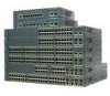
Cisco 2960G-8TC Hardware Installation Guide
Cisco 2960G-8TC - Catalyst Switch Manual
 |
UPC - 882658120329
View all Cisco 2960G-8TC manuals
Add to My Manuals
Save this manual to your list of manuals |
Cisco 2960G-8TC manual content summary:
- Cisco 2960G-8TC | Hardware Installation Guide - Page 1
Catalyst 2960 Switch Hardware Installation Guide March 2010 Americas Headquarters Cisco Systems, Inc. 170 West Tasman Drive San Jose, CA 95134-1706 USA http://www.cisco.com Tel: 408 526-4000 800 553-NETS (6387) Fax: 408 527-0883 Text Part Number: OL-7075-09 - Cisco 2960G-8TC | Hardware Installation Guide - Page 2
with the instruction manual, may cause command display output, and figures included in the document are shown for illustrative purposes only. Any use of actual IP addresses in illustrative content is unintentional and coincidental. Catalyst 2960 Switch Hardware Installation Guide © 2005-2010 Cisco - Cisco 2960G-8TC | Hardware Installation Guide - Page 3
2960G-24TC-L and Catalyst 2960G-48TC-L Switches 1-8 Catalyst 2960 8-Port Switches 1-9 Catalyst 2960PD-8TT-L Switch 1-9 Catalyst 2960-8TC-S, Catalyst 2960-8TC-L, and Catalyst 2960G-8TC -L Switches 1-10 10/100 Ports 1-11 10/100/1000 Ports 1-11 PoE Ports (Only Catalyst 2960 PoE Switches) 1-12 SFP - Cisco 2960G-8TC | Hardware Installation Guide - Page 4
2-5 Tools and Equipment 2-5 Verifying Switch Operation 2-5 Installing the Switch 2-6 Rack-Mounting 2-6 Removing Screws from the Switch 2-7 Attaching Brackets to the Catalyst 2960 Switch 2-7 Mounting the Switch in a Rack 2-10 Attaching the Cable Guide 2-11 Wall-Mounting 2-11 Attaching the Brackets to - Cisco 2960G-8TC | Hardware Installation Guide - Page 5
Wall-Mounting (with Rack-Mount Brackets) 3-16 Where to Go Next 3-18 Troubleshooting 4-1 Diagnosing Problems 4-1 Verify Switch POST Results 4-2 Monitor Switch LEDs 4-2 Verify Switch Connections 4-2 Bad or Damaged Cable 4-2 Ethernet and Fiber Cables 4-3 Link Status 4-3 Transceiver Module Port Issues - Cisco 2960G-8TC | Hardware Installation Guide - Page 6
Through the Console Port C-2 Connecting to the Console Port C-3 Starting the Terminal Emulation Software C-3 Connecting to a Power Source C-4 Entering the Initial Configuration Information C-4 IP Settings C-5 Completing the Setup Program C-5 Catalyst 2960 Switch Hardware Installation Guide vi OL - Cisco 2960G-8TC | Hardware Installation Guide - Page 7
configuration guide, the switch command reference, and the switch system message guide on the Cisco.com Product Documentation home page. For information about the standard Cisco IOS Release 12.1 or 12.2 commands, see the Cisco IOS documentation set from the Cisco.com home page by choosing Support - Cisco 2960G-8TC | Hardware Installation Guide - Page 8
2960 Switch System Message Guide • Device manager online help (available on the switch) • Cisco Network Assistant online help (available on the switch) • Catalyst 2960 Switches Getting Started Guide (8-Port Switches) • Catalyst 2960 Switch Getting Started Guide. This guide is for the 24- and 48-port - Cisco 2960G-8TC | Hardware Installation Guide - Page 9
in Cisco Product Documentation as a Really Simple Syndication (RSS) feed and set content to be delivered directly to your desktop using a reader application. The RSS feeds are a free service and Cisco currently supports RSS Version 2.0. OL-7075-09 Catalyst 2960 Switch Hardware Installation Guide - Cisco 2960G-8TC | Hardware Installation Guide - Page 10
Preface Catalyst 2960 Switch Hardware Installation Guide x OL-7075-09 - Cisco 2960G-8TC | Hardware Installation Guide - Page 11
configuration guide for deployment examples. Table 1-1 describes the switch model features. Table 1-1 Catalyst 2960 Switch Model Descriptions Switch Model Catalyst 2960-8TC-S Catalyst 2960-24-S Catalyst 2960-24TC-S Catalyst 2960-48TC-S Catalyst 2960-48TT-S Catalyst 2960-48PST-S Catalyst 2960 - Cisco 2960G-8TC | Hardware Installation Guide - Page 12
2960G-8TC-L Catalyst 2960PD-8TT-L Catalyst 2960-24LT-L Catalyst 2960-24PC-L Catalyst 2960-24TC-L Catalyst 2960G-24TC-L Catalyst 2960-24TT-L Catalyst 2960-48PST-L Catalyst 2960-48TC-L Catalyst 2960G-48TC-L Catalyst 2960-48TT-L Supported Software Image Description LAN-Lite 24 10/100BASE-TX ports - Cisco 2960G-8TC | Hardware Installation Guide - Page 13
SFP modules. The Catalyst 2960-8TC-S, Catalyst 2960-24TC-S, and Catalyst 2960-48TC-S switches support only 1000BASE-LX/LH, 1000BASE-SX, and 100BASE-FX SFP modules. The Catalyst 2960-8TC-L, 2960G-8TC-L, and 2960-8TC-S switches do not support the 1000BASE-T or GLC-GE-100FX SFP modules. For specific - Cisco 2960G-8TC | Hardware Installation Guide - Page 14
2960 24- and 48-port switches: • Catalyst 2960-24-S, 2960-24TC-S, 2960-48TC-S, and 2960-48TT-S Switches, page 1-4 • Catalyst 2960-24PC-L, 2960-24PC-S, 2960-24LC-S, 2960-24TC-L, 2960-48TC-L, 2960-24LT-L, 2960-24TT-L, 2960-48TT-L, 2960-48PST-L, and 2960-48PST-S Switches, page 1-6 • Catalyst 2960G-24TC - Cisco 2960G-8TC | Hardware Installation Guide - Page 15
2960-24TC-S Switch Front Panel Catalyst 2960 Series SI 204631 1 2 1 10/100 ports 2 Dual-purpose ports Figure 1-3 Catalyst 2960-48TC-S Switch Front Panel SYST STAT DUPLX SPEED MODE 1 2 3 4 5 6 7 8 9 10 11 12 13 14 15 16 17 18 19 20 21 22 23 24 25 26 27 28 29 30 31 32 33 - Cisco 2960G-8TC | Hardware Installation Guide - Page 16
13X 23X Catalyst 2960 Series PoE-24 2X POWER OVER ETHERNET 12X 14X 1 2 24X 204641 1 2 1 10/100 PoE ports 2 Dual-purpose ports Figure 1-6 Catalyst 2960-24PC-S Switch Front Panel 206731 1 2 1 10/100 PoE ports 2 Dual-purpose ports Figure 1-7 Catalyst 2960-24LC-S Switch Front Panel - Cisco 2960G-8TC | Hardware Installation Guide - Page 17
13 14 15 16 17 18 19 20 21 22 23 24 Catalyst 2960 Series PoE-8 11X 13X 23X 2X POWER OVER ETHERNET 12X 14X 1 2 24X 1 2 3 1 10/100 PoE ports 3 10/100/1000 uplink ports 2 10/100 ports Figure 1-11 Catalyst 2960-24TT-L Switch Front Panel 204607 SYST RPS STAT DUPLX SPEED MODE 1 2 1 10 - Cisco 2960G-8TC | Hardware Installation Guide - Page 18
SFP module slots Figure 1-14 Catalyst 2960-48PST-S Switch Front Panel 3 206732 1 2 1 10/100 PoE ports 2 10/100/1000 uplink ports 3 SFP module slots Catalyst 2960G-24TC-L and Catalyst 2960G-48TC-L Switches The 10/100/1000 ports on the Catalyst 2960G-24TC-L and Catalyst 2960G-48TC-L switches - Cisco 2960G-8TC | Hardware Installation Guide - Page 19
• Catalyst 2960-8TC-S, Catalyst 2960-8TC-L, and Catalyst 2960G-8TC -L Switches, page 1-10 Catalyst 2960PD-8TT-L Switch The Catalyst 2960PD-8TT-L (Figure 1-17) switch front panel has a console port, eight 10/100 ports, and a 10/100/1000 uplink port that can receive power from an upstream PoE switch - Cisco 2960G-8TC | Hardware Installation Guide - Page 20
2960-8TC-L, and Catalyst 2960G-8TC -L Switches The console ports for the Catalyst 2960-8TC-S, Catalyst 2960-8TC-L, and Catalyst 2960G-8TC-L switches (Figure 1-18 to Figure 1-20) are on the front panels. The switches also have a dual-purpose port that can use either an RJ-45 connector or an SFP - Cisco 2960G-8TC | Hardware Installation Guide - Page 21
/1000 or 1000BASE-T SFP module port on the switch, regardless of the type of device on the other end of the connection. For configuration information for this feature, see the switch software configuration guide or the switch command reference. OL-7075-09 Catalyst 2960 Switch Hardware Installation - Cisco 2960G-8TC | Hardware Installation Guide - Page 22
. The Auto setting is the default. - Never: When you select the Never setting, the port does not provide power even if a Cisco IP phone or an access point is connected. • You also can connect a Cisco IP Phone or Cisco Aironet Access Point to a Catalyst 2960 PoE switch 10/100 port and to an AC - Cisco 2960G-8TC | Hardware Installation Guide - Page 23
an SFP module connector. The dual front ends are not redundant interfaces. The switch activates only one connector of the pair at a time. By default, the switch dynamically selects the interface type that first links up. However, you can use the media-type interface configuration command to manually - Cisco 2960G-8TC | Hardware Installation Guide - Page 24
configure and to monitor individual switches and switch clusters. Only the Catalyst 2960 PoE switches have a PoE LED. The four Catalyst 2960 8-port switches and these models do not have an RPS connector or an RPS LED: Catalyst 2960-24-S, Catalyst 2960-24TC-S, Catalyst 2960-48TT-S, Catalyst 2960-48TC - Cisco 2960G-8TC | Hardware Installation Guide - Page 25
9 10 11 12 11X 1 SYST LED 5 Speed LED 2 RPS LED 6 PoE LED1 3 Status LED 7 Mode button 4 Duplex LED 8 Port LEDs 1. The PoE LED is only on the Catalyst 2960 PoE switches. The System LED shows whether the system is receiving power and is functioning properly. Table 1-2 lists the LED colors and their - Cisco 2960G-8TC | Hardware Installation Guide - Page 26
Port status The port status. This is the default mode. DUPLX SPEED1 PoE2 Port duplex mode Port speed PoE port power The port duplex mode: full duplex or half duplex. The port operating speed: 10, 100, or 1000 Mb/s. The PoE status. 1. When installed in Catalyst 2960 switches, 1000BASE-T SFP - Cisco 2960G-8TC | Hardware Installation Guide - Page 27
selected, the PoE LED shows PoE problems when they are detected (Table 1-5). The PoE LED applies only to Catalyst 2960 switches that support PoE. Table 1-5 PoE Mode LED Color Off Green Blinking amber PoE Status PoE mode is not selected. None of the 10/100 PoE ports have been denied power or are - Cisco 2960G-8TC | Hardware Installation Guide - Page 28
. The Catalyst 2960-24LT-L and 2960-24LC-S switches provide up to 124 W of power. Blinking amber PoE is off due to a fault. Amber Caution PoE faults are caused when noncompliant cabling or powered devices are connected to a PoE port. Only standard-compliant cabling can be used to connect Cisco - Cisco 2960G-8TC | Hardware Installation Guide - Page 29
-C2960-8TC: Catalyst 2960-8TC-L, 2960-8TC-S, and 2960PD-8TT-L switches • CBLGRD-C2960G-8TC: Cisco Catalyst 2960G-8TC switch Rear Panel Description • Internal Power Supply, page 1-20 • Cisco RPS, page 1-20 • Console Port, page 1-21 Depending on the Catalyst 2960 switch model, the switch can have - Cisco 2960G-8TC | Hardware Installation Guide - Page 30
Note These Catalyst 2960 switches do not have an RPS connector: Catalyst 8-port switches, 2960-24-S, 2960-24TC-S, 2960-48TC-S, 2960-48TT-S, 2960-48PST-S, 2960-24PC-S, and 2960-24LC-S switches. Note These Catalyst 2960 switches support only the Cisco RPS 2300: Catalyst 2960-24PC-L, 2960-24LT-L, and - Cisco 2960G-8TC | Hardware Installation Guide - Page 31
DTE adapter. You can order a kit (part number ACS-DSBUASYN=) containing that adapter from Cisco. For console port and adapter pinout information, see the "Connector and Cable Specifications" section on page B-1. Note The console port on the Catalyst 2960 8-port switches is on the front panel rather - Cisco 2960G-8TC | Hardware Installation Guide - Page 32
by connecting your management station directly to the switch console port or by using Telnet from a remote management station. See the Catalyst 2960 Switch Command Reference on Cisco.com for more information. For setup instructions that use the CLI, go to Appendix C, "Configuring the Switch with the - Cisco 2960G-8TC | Hardware Installation Guide - Page 33
information for all Catalyst 2960 switches, except for the Catalyst 2960-8TC-S, 2960-8TC-L, 2960G-8T-LC, 2960-48PST-L, and 2960PD-8TT-L switches. For those switches, see Chapter 3, "Switch Installation (8-Port Switches)." The instructions in this chapter for connecting to the switch ports and for - Cisco 2960G-8TC | Hardware Installation Guide - Page 34
Preparing for Installation Chapter 2 Switch Installation (24- and 48-Port Switches) Warnings These warnings are translated into several languages in the Regulatory Compliance and Safety Information for the Catalyst 2960 Switch guide. Warning To prevent the switch from overheating, do not - Cisco 2960G-8TC | Hardware Installation Guide - Page 35
Chapter 2 Switch Installation (24- and 48-Port Switches) Preparing for Installation Warning To prevent bodily injury when mounting or servicing this unit in a rack, you must take special precautions to ensure that the system remains stable. The following guidelines are provided to ensure your - Cisco 2960G-8TC | Hardware Installation Guide - Page 36
the specifications in Table B-1 on page B-5, which lists the cable specifications for 1000BASE-X and 100BASE-X SFP modules for the Catalyst 2960 switch. Catalyst 2960 switch SFP ports can use both GLC-GE-100XX and GLC-FE-100XX SFP modules. Catalyst 2960 Switch Hardware Installation Guide 2-4 OL - Cisco 2960G-8TC | Hardware Installation Guide - Page 37
contact your Cisco representative or reseller for support. Tools and Equipment You need to supply a number-2 Phillips screwdriver to rack-mount the switch. Verifying Switch Operation Before you install the switch in a rack, on a wall, or on a table or shelf, you should power on the switch and verify - Cisco 2960G-8TC | Hardware Installation Guide - Page 38
to those switches, see Chapter 3, "Switch Installation (8-Port Switches)." The illustrations in this section might not show your specific switch; however, the instructions apply to all 24- and 48-port switches. Warning To prevent bodily injury when mounting or servicing this unit in a rack, you - Cisco 2960G-8TC | Hardware Installation Guide - Page 39
(24- and 48-Port Switches) Installing the Switch To install the switch in a 19-inch or 24-inch rack (24-inch racks require optional mounting hardware), follow the instructions described in these sections: • Removing Screws from the Switch, page 2-7 • Attaching Brackets to the Catalyst 2960 Switch - Cisco 2960G-8TC | Hardware Installation Guide - Page 40
(24- and 48-Port Switches) Figure 2-2 1 Attaching Brackets for 19-Inch Racks to a Catalyst 2960 Switch, Front Panel Forward 11XX SYST RPS STAT DUPLX 111X SPEED 2X MODE 12X 204614 1 Phillips flat-head screws Figure 2-3 Attaching Brackets for 24-Inch Racks to a Catalyst 2960 Switch - Cisco 2960G-8TC | Hardware Installation Guide - Page 41
Chapter 2 Switch Installation (24- and 48-Port Switches) Installing the Switch Figure 2-5 Attaching Brackets for 24-Inch Racks to a Catalyst 2960 Switch, Rear Panel Forward 137076 1 1 Phillips flat-head screws Figure 2-6 Attaching Brackets for 19-Inch Telco Racks to a Catalyst 2960 Switch 1X - Cisco 2960G-8TC | Hardware Installation Guide - Page 42
After the switch is mounted in the rack, do these tasks to complete the installation: • Power on the switch. See the "Verifying Switch Operation" section on page 2-5. • Connect to a 10/100 or 10/100/1000 port, and run Express Setup. See the Catalyst 2960 Switch Getting Started Guide for instructions - Cisco 2960G-8TC | Hardware Installation Guide - Page 43
SPEED MODE 204619 1 Cable guide screw Wall-Mounting This section does not apply to the Catalyst 2960 8-port switches. For information applicable to those switches, see Chapter 3, "Switch Installation (8-Port Switches)." To install the switch on a wall, follow the instructions in these sections - Cisco 2960G-8TC | Hardware Installation Guide - Page 44
Phillips pan-head screws to attach the RPS connector cover to the back of the switch, as shown in Figure 2-11. Note The Catalyst 2960 8-port switches and the Catalyst 2960-24-S, 2960-24TC-S, 2960-48TT-S, and 2960-48TC-S switches do not have an RPS connector. Warning If an RPS is not connected to - Cisco 2960G-8TC | Hardware Installation Guide - Page 45
Chapter 2 Switch Installation (24- and 48-Port Switches) Installing the Switch Mounting the Switch on a Wall For the best support of the switch and cables, make sure the switch is attached securely to wall studs or to a firmly attached plywood mounting backboard. Mount the switch with the front - Cisco 2960G-8TC | Hardware Installation Guide - Page 46
to all switches except the Catalyst 2960-8TC-L, 2960-8TC-S, 2960G-8TC-L, and 2960PD-8TT-L switches. For information applicable to those switches, see Chapter 3, "Switch Installation (8-Port Switches)." Step 1 Step 2 Locate the adhesive strip with the rubber feet in the mounting-kit envelope - Cisco 2960G-8TC | Hardware Installation Guide - Page 47
the list of SFP modules that the Catalyst 2960 switch supports. Each SFP module must be of the same type as the SFP module on the other end of the cable, and the cable must not exceed the stipulated cable length for reliable communications. See the "SFP Module Cable Specifications" section on page - Cisco 2960G-8TC | Hardware Installation Guide - Page 48
(24- and 48-Port Switches) stipulations for SFP module connections. Use only Cisco SFP modules on the Catalyst 2960 switch. Cisco SFP modules and the Catalyst 2960 switch support the Quality ID feature. Only SFP modules with the Quality ID feature are supported. For detailed instructions on - Cisco 2960G-8TC | Hardware Installation Guide - Page 49
Chapter 2 Switch Installation (24- and 48-Port Switches) Installing and Removing SFP Modules Figure 2-15 Installing an SFP Module into an SFP Module Slot 1X Catalyst 2960 Series SI 11X 1 2 204639 1 1 SFP module Step 5 Remove the dust plugs from the SFP module optical ports and store them - Cisco 2960G-8TC | Hardware Installation Guide - Page 50
the port and cabling stipulations in the "Installation Guidelines" section on page 2-4 and in the "SFP Module Slots" section on page 1-13. See Appendix B, "Connector and Cable Specifications" for information about the LC on the SFP module. 2-18 Catalyst 2960 Switch Hardware Installation Guide OL - Cisco 2960G-8TC | Hardware Installation Guide - Page 51
Chapter 2 Switch Installation (24- and 48-Port Switches) Connecting to SFP Modules Step 1 Remove the rubber plugs from the module port and fiber-optic cable, and store them for future use. Step 2 Insert one end of the fiber-optic cable into the SFP module port (see Figure 2-17). Figure 2-17 - Cisco 2960G-8TC | Hardware Installation Guide - Page 52
Connecting to a Dual-Purpose Port Chapter 2 Switch Installation (24- and 48-Port Switches) Note The auto-MDIX feature is enabled by default. For configuration information for this feature, see the switch software configuration guide or the switch command reference. Figure 2-18 Connecting to a - Cisco 2960G-8TC | Hardware Installation Guide - Page 53
as a member of a cluster or as an individual switch. See the Catalyst 2960 Switch Software Configuration Guide and the Catalyst 2960 Switch Command Reference on Cisco.com for information on using the CLI with a Catalyst 2960 switch. • Start an SNMP application such as the CiscoView application - Cisco 2960G-8TC | Hardware Installation Guide - Page 54
Where to Go Next Chapter 2 Switch Installation (24- and 48-Port Switches) 2-22 Catalyst 2960 Switch Hardware Installation Guide OL-7075-09 - Cisco 2960G-8TC | Hardware Installation Guide - Page 55
in this chapter is specific to the Catalyst 2960-8TC-S, Catalyst 2960-8TC-L, Catalyst 2960G-8TC-L, and Catalyst 2960PD-8TT-L switches. For installation information applicable to the other Catalyst 2960 switches, see Chapter 2, "Switch Installation (24- and 48-Port Switches)." Read the topics and - Cisco 2960G-8TC | Hardware Installation Guide - Page 56
before mounting or servicing the unit in the rack. Statement 1006 Warning Class 1 laser product. Statement 1008 Warning The plug-socket combination must be accessible at all times, because it serves as the main disconnecting device. Statement 1019 Catalyst 2960 Switch Hardware Installation Guide - Cisco 2960G-8TC | Hardware Installation Guide - Page 57
1074 Installation Guidelines This section is specific to the Catalyst 2960 8-port switches. For information applicable to the other Catalyst 2960 switches, see Chapter 2, "Switch Installation (24- and 48-Port Switches)." When you determine where to place the switch, be sure to observe these - Cisco 2960G-8TC | Hardware Installation Guide - Page 58
on the 1000BASE-ZX SFP module at each end of the link. Equipment That You Supply This section is specific to the Catalyst 2960 8-port switches. For information applicable to the other Catalyst 2960 switches, see Chapter 2, "Switch Installation (24- and 48-Port Switches)." You need this equipment - Cisco 2960G-8TC | Hardware Installation Guide - Page 59
Switch Installation (8-Port Switches) Verifying Switch Operation Installing the Catalyst 2960 8-port switches in a 19-inch rack requires an optional bracket kit that is not included with the switch. You can order a kit containing the 19-inch rack-mounting brackets and hardware from Cisco. The kit - Cisco 2960G-8TC | Hardware Installation Guide - Page 60
Mounting (with Rack-Mount Brackets), page 3-16 Desk- or Shelf-Mounting (without Mounting Screws) This section is specific to the Catalyst 2960 8-port switches. For information applicable to the other Catalyst 2960 switches, see Chapter 2, "Switch Installation (24- and 48-Port Switches)." The switch - Cisco 2960G-8TC | Hardware Installation Guide - Page 61
3 Switch Installation (8-Port Switches) Installing the Switch Desk- or Shelf-Mounting (with Mounting Screws) This section is specific to the Catalyst 2960 8-port switches. For information applicable to the other Catalyst 2960 switches, see Chapter 2, "Switch Installation (24- and 48-Port Switches - Cisco 2960G-8TC | Hardware Installation Guide - Page 62
C, "Configuring the Switch with the CLI-Based Setup Program." Under the Desk- or Shelf-Mounting (with Mounting Screws) This section is specific to the Catalyst 2960 8-port switches. For information applicable to the other Catalyst 2960 switches, see Chapter 2, "Switch Installation (24- and 48-Port - Cisco 2960G-8TC | Hardware Installation Guide - Page 63
onto the mounting screws, and slide the switch forward until it locks in place, as shown in Figure 3-4. Note We strongly recommend that you allow at least 3 inches (7.6 cm) of clearance around the ventilation openings to prevent airflow restriction and overheating. OL-7075-09 Catalyst 2960 Switch - Cisco 2960G-8TC | Hardware Installation Guide - Page 64
"Connecting to a Dual-Purpose Port" section on page 2-20 to complete the installation. For configuration instructions about using the CLI setup program, go to Appendix C, "Configuring the Switch with the CLI-Based Setup Program." 3-10 Catalyst 2960 Switch Hardware Installation Guide OL-7075-09 - Cisco 2960G-8TC | Hardware Installation Guide - Page 65
3 Switch Installation (8-Port Switches) Installing the Switch Wall-Mounting (with Mounting Screws) This section is specific to the Catalyst 2960 8-port switches. For information applicable to the other Catalyst 2960 switches, see Chapter 2, "Switch Installation (24- and 48-Port Switches)." The - Cisco 2960G-8TC | Hardware Installation Guide - Page 66
Installing the Switch Chapter 3 Switch Installation (8-Port Switches) Figure 3-5 Installing the Mounting Screws on a Wall 1 2 switch onto the mounting screws, and slide it down until it locks in place, as shown in Figure 3-6. 3-12 Catalyst 2960 Switch Hardware Installation Guide - Cisco 2960G-8TC | Hardware Installation Guide - Page 67
"Connecting to a Dual-Purpose Port" section on page 2-20 to complete the installation. For configuration instructions about using the CLI setup program, go to Appendix C, "Configuring the Switch with the CLI-Based Setup Program." OL-7075-09 Catalyst 2960 Switch Hardware Installation Guide 3-13 - Cisco 2960G-8TC | Hardware Installation Guide - Page 68
Installing the Switch Chapter 3 Switch Installation (8-Port Switches) Magnet Mounting This section is specific to the Catalyst 2960 8-port switches. For information applicable to the other Catalyst 2960 switches, see Chapter 2, "Switch Installation (24- and 48-Port Switches)." Step 1 Place one - Cisco 2960G-8TC | Hardware Installation Guide - Page 69
Chapter 2, "Switch Installation (24- and 48-Port Switches)." Installing the Catalyst 2960 8-port switches in a 19-inch rack requires an optional bracket kit that is not included with the switch. You can order a kit containing the 19-inch rack-mounting brackets and hardware from Cisco. The kit part - Cisco 2960G-8TC | Hardware Installation Guide - Page 70
rack-mounting brackets and hardware from Cisco. The kit part number is RCKMNT-19-CMPCT=. This section is specific to the Catalyst 2960 8-port switches. For information applicable to the other Catalyst 2960 switches, see Chapter 2, "Switch Installation (24- and 48-Port Switches)." 3-16 Catalyst - Cisco 2960G-8TC | Hardware Installation Guide - Page 71
After the switch is mounted on the wall, do these tasks to complete the installation: 1. Power on the switch. See the "Verifying Switch Operation" section on page 3-5. 2. Connect to a 10/100 or 10/100/1000 port, and run Express Setup. See the switch getting started guide for instructions. 3. Connect - Cisco 2960G-8TC | Hardware Installation Guide - Page 72
as a member of a cluster or as an individual switch. See the Catalyst 2960 Switch Software Configuration Guide and the Catalyst 2960 Switch Command Reference on Cisco.com for information on using the CLI with a Catalyst 2960 switch. • Start an SNMP application such as the CiscoView application - Cisco 2960G-8TC | Hardware Installation Guide - Page 73
Network Management Protocol (SNMP) workstation. See the software configuration guide, the switch command reference guide on Cisco.com, or the documentation that came with your SNMP application for details. This chapter describes these topics for troubleshooting problems: • Diagnosing Problems, page - Cisco 2960G-8TC | Hardware Installation Guide - Page 74
Cisco technical support representative if your switch does not pass POST. Monitor Switch LEDs Look at the port LEDs for troubleshooting information about the switch in another port or interface to see if the problem also exists there. Catalyst 2960 Switch Hardware Installation Guide 4-2 OL-7075-09 - Cisco 2960G-8TC | Hardware Installation Guide - Page 75
privileged EXEC command to verify the port or module error-disabled, disabled, or shutdown status. Re-enable the port if necessary. • Make sure that all you have properly cleaned and securely connected all fiber-optic connections. OL-7075-09 Catalyst 2960 Switch Hardware Installation Guide 4-3 - Cisco 2960G-8TC | Hardware Installation Guide - Page 76
configuration guide. Monitor Switch Performance Review these sections when you troubleshoot switch performance problems: • Speed, Duplex, and Autonegotiation, page 4-4 • Autonegotiation and NIC Cards, page 4-5 • Cabling Distance, page 4-5 Speed, Duplex, and Autonegotiation If the port statistics - Cisco 2960G-8TC | Hardware Installation Guide - Page 77
cards (NICs). By default, the switch ports and interfaces are set to autonegotiate. It is common for devices such as laptop computers or other devices to also be set to autonegotiate, yet sometimes autonegotiation issues occur. To troubleshoot autonegotiation problems, try to manually set both sides - Cisco 2960G-8TC | Hardware Installation Guide - Page 78
24PC-S, 2960-24LC-S, 2960-48PST-S, and 2960G-48TC-L Switches 140035, 0781-00374-01 SN: XXXNNNNXXXX Cisco 11-character label Figure 4-2 Serial Number Location on the Catalyst 2960-24-S, 2960-24TC-S, and 2960-48TC-S Switches 191931 SN: XXXNNNNXXXX Catalyst 2960 Switch Hardware Installation Guide - Cisco 2960G-8TC | Hardware Installation Guide - Page 79
Chapter 4 Troubleshooting Locating the Switch Serial Number Figure 4-3 Serial Number Location on the Catalyst 2960-8TC-L, Catalyst 2960G-8TC-L, Catalyst 2960-8TC-S, and Catalyst 2960PD-8TT-L Switches 200186 SN: XXXNNNNXXXX OL-7075-09 Catalyst 2960 Switch Hardware Installation Guide 4-7 - Cisco 2960G-8TC | Hardware Installation Guide - Page 80
Locating the Switch Serial Number Chapter 4 Troubleshooting Catalyst 2960 Switch Hardware Installation Guide 4-8 OL-7075-09 - Cisco 2960G-8TC | Hardware Installation Guide - Page 81
Catalyst 2960-24TT-L Switch Specifications • Table A-5 on page A-3, Catalyst 2960-48TC-L, 2960-48TT-S, and 2960-48TT-L Switch Specifications • Table A-6 on page A-3, Catalyst 2960G-24TC-L and Catalyst 2960G-48TC-L Switch Specifications • Table A-7 on page A-4, Catalyst 2960-8TC-L, 2960G-8TC-L, 2960 - Cisco 2960G-8TC | Hardware Installation Guide - Page 82
hour (Catalyst 2960-48TC-S) • 0.05 KVA (Catalyst 2960-24-S and 2960-24TC-S) • 0.075 KVA (Catalyst 2960-48TC-S) 8 lb (3.63 kg) 1.73 x 9.3 x 17.5 in. (4.39 x 23.62 x 44.45 cm) Table A-3 Catalyst 2960-24PC-L, Catalyst 2960-24LT-L, and Catalyst 2960-48PST-L Switch Specifications Power Requirements - Cisco 2960G-8TC | Hardware Installation Guide - Page 83
-24TC-L) 140 W, 477 BTUs per hour (Catalyst 2960G-48TC-L) 0.075 KVA (Catalyst 2960G-24TC-L 0.14 KVA (Catalyst 2960G-48TC-L 10 lb (4.54 kg) (Catalyst 2960G-24T-L) 12 lb (5.44 kg) (Catalyst 2960G-48TC-L 1.73 x 12.9 x 17.5 in. (4.39 x 32.76 x 44.45 cm) Catalyst 2960 Switch Hardware Installation Guide - Cisco 2960G-8TC | Hardware Installation Guide - Page 84
Specifications Table A-7 Catalyst 2960-8TC-L, 2960G-8TC-L, 2960-8TC-S, and 2960PD-8TT-L Switch Specifications Power Requirements AC input voltage DC input voltage Power consumption Power rating 100 to 240 VAC (autoranging) 0.5 to 0.25 A, 50 to 60 Hz (Catalyst 2960-8TC-L and Catalyst 2960-8TC - Cisco 2960G-8TC | Hardware Installation Guide - Page 85
-S Switch Specifications Power Requirements AC input voltage DC input voltage for RPS 2300 Power consumption1 100 to 240 VAC (autoranging) 8 to 4 A, 50 to 60 Hz (Catalyst 2960-24PC-S) 3 to 1.5 A, 50 to 60 Hz (Catalyst 2960-24LC-S) 5 to 2 A, 50 to 60 Hz (Catalyst 2960-48PST-S) +12 V @11.25 A, -48 - Cisco 2960G-8TC | Hardware Installation Guide - Page 86
Appendix A Technical Specifications Catalyst 2960 Switch Hardware Installation Guide A-6 OL-7075-09 - Cisco 2960G-8TC | Hardware Installation Guide - Page 87
100/1000 Ethernet ports on the Catalyst 2960 switch use standard RJ-45 connectors. Figure B-1 shows the pinout. Note The auto-MDIX feature is enabled by default. For configuration information for this feature, see the switch software configuration guide or the switch command reference. Connecting to - Cisco 2960G-8TC | Hardware Installation Guide - Page 88
a crossover cable to connect two ports when both ports are designated with an X or when both ports do not have an X. Figure B-1 Pin 1 2 3 4 5 6 7 8 10/100/1000 Port Pinouts Label TP0+ TP0TP1+ TP2+ TP2TP1TP3+ TP3- 12345678 60915 Catalyst 2960 Switch Hardware Installation Guide B-2 OL-7075-09 - Cisco 2960G-8TC | Hardware Installation Guide - Page 89
ports. See the Catalyst 2960 switch release notes for a list of supported SFP modules. Note The auto-MDIX feature is enabled by default. For configuration information for this feature, see the switch software configuration guide or the switch command reference. OL-7075-09 Catalyst 2960 Switch - Cisco 2960G-8TC | Hardware Installation Guide - Page 90
. You can order a kit (part number ACS-DSBUASYN=) containing that adapter from Cisco. For console port and adapter pinout information, see Table B-2 and Table B-3. Cable and Adapter Specifications These sections describe the cables and adapters used with Catalyst 2960 switches: • SFP Module Cable - Cisco 2960G-8TC | Hardware Installation Guide - Page 91
greater than 984 feet (300 m). 4. 1000BASE-ZX SFP modules can send data up to 62 miles (100 km) by using dispersion-shifted SMF or low-attenuation SMF; the distance depends on the fiber quality, the number of splices, and the connectors. OL-7075-09 Catalyst 2960 Switch Hardware Installation - Cisco 2960G-8TC | Hardware Installation Guide - Page 92
on Catalyst 2960 switches. Figure B-7 Switch 1 TPO+ 2 TPO3 TP1+ 6 TP1- Four Twisted-Pair Straight-Through Cable Schematic for 10/100/1000 Ports Router or PC 1 TP1+ 2 TP13 TPO+ 6 TPO- 4 TP2+ 5 TP27 TP3+ 8 TP3- 4 TP3+ 5 TP37 TP2+ 8 TP2- 65272 Catalyst 2960 Switch Hardware Installation Guide - Cisco 2960G-8TC | Hardware Installation Guide - Page 93
/1000 Ports Switch 1 TP0+ 2 TP03 TP1+ 6 TP1- 4 TP2+ 5 TP27 TP3+ 8 TP3- Crossover Cable and Adapter Pinouts This section describes how to identify a crossover cable and also describes the adapter pinouts. Identifying a Crossover Cable To identify a crossover cable, compare the two modular ends of - Cisco 2960G-8TC | Hardware Installation Guide - Page 94
from Cisco. Table B-3 Switch Console Port (DTE) Signal RTS DTR TxD GND GND RxD DSR CTS Console Port Signaling Using a DB-25 Adapter RJ-45-to-DB-25 Terminal Adapter DB-25 Pin 5 6 3 7 7 2 20 4 Console Device Signal CTS DSR RxD GND GND TxD DTR RTS Catalyst 2960 Switch Hardware Installation Guide - Cisco 2960G-8TC | Hardware Installation Guide - Page 95
power source, review the safety warnings in Chapter 2, "Switch Installation (24- and 48-Port Switches)," and Chapter 3, "Switch Installation (8-Port Switches)." For installation procedures for mounting your switch, connecting to the switch ports, or connecting to the small form-factor pluggable (SFP - Cisco 2960G-8TC | Hardware Installation Guide - Page 96
to connect the switch ports to other Ethernet devices. Note The auto-MDIX feature is enabled by default. For configuration information for this feature, see the switch software configuration guide or the switch command reference. Catalyst 2960 Switch Hardware Installation Guide C-2 OL-7075-09 - Cisco 2960G-8TC | Hardware Installation Guide - Page 97
-DB-9 adapter cable, insert the RJ-45 connector into the console port on the rear of a switch, as shown in Figure C-1. Figure C-1 Connecting a Switch to a PC 1 CONSOLE 137088 3 2 1 Catalyst 2960 switch 3 RJ-45-to-DB-9 adapter cable 2 Power cord Step 2 Attach the DB-9 female DTE of the adapter - Cisco 2960G-8TC | Hardware Installation Guide - Page 98
an IP address and other configuration information necessary for the switch to communicate with the local routers and the Internet. This information is also required if you plan to use the Network Assistant to configure and manage the switch. Catalyst 2960 Switch Hardware Installation Guide C-4 OL - Cisco 2960G-8TC | Hardware Installation Guide - Page 99
Enter a virtual terminal (Telnet) password, and press Return. The password can be from 1 to 25 alphanumeric characters, is case sensitive, allows spaces, but ignores leading spaces. Enter virtual terminal password: terminal-password OL-7075-09 Catalyst 2960 Switch Hardware Installation Guide C-5 - Cisco 2960G-8TC | Hardware Installation Guide - Page 100
FastEthernet0/3 ! ... ! interface GigabitEthernet0/28 ! end Step 10 These choices appear: [0] Go to the IOS command prompt without saving this config. [1] Return back to the setup without saving this config. Catalyst 2960 Switch Hardware Installation Guide C-6 OL-7075-09 - Cisco 2960G-8TC | Hardware Installation Guide - Page 101
the network by using Telnet. For configuration information, see the switch software configuration guide or the switch command reference. To use the Network Assistant, see the Getting Started with Cisco Network Assistant guide on Cisco.com. OL-7075-09 Catalyst 2960 Switch Hardware Installation - Cisco 2960G-8TC | Hardware Installation Guide - Page 102
Entering the Initial Configuration Information Appendix C Configuring the Switch with the CLI-Based Setup Program Catalyst 2960 Switch Hardware Installation Guide C-8 OL-7075-09 - Cisco 2960G-8TC | Hardware Installation Guide - Page 103
13 10/100 ports 1-11 10/100 ports PoE 1-12 19- and 24-inch racks 2-7, 3-15 A AC power connecting to 2-5, 3-5 connector 1-20 specifications A-2 to A-4 AC power adapter for Catalyst 2960PD-8TT-L switch 1-13 adapter pinouts, terminal RJ-45-to-DB-25 B-8 RJ-45-to-DB-9 B-8 attaching the Cisco RPS warning - Cisco 2960G-8TC | Hardware Installation Guide - Page 104
, four twisted-pair, 1000BASE-T ports B-7 D DC power RPS 1-3 IN-2 Catalyst 2960 Switch Hardware Installation Guide descriptions of switch models 1-1 desk-mounting 2-14, 3-6 device manager described 1-22 to configure switch 2-21, 3-18 diagnosing problems 4-1 disconnecting device warning 2-3 dual - Cisco 2960G-8TC | Hardware Installation Guide - Page 105
attaching 2-7 to 2-9 rack-mount 2-10, 3-16 N Network Assistant described 1-22 to configure switch 2-21, 3-18 network configuration examples 1-1 noise, electrical 2-5, 3-4 no user-serviceable parts warning 2-4 O overheating warning 2-2, 3-1 Catalyst 2960 Switch Hardware Installation Guide IN-3 - Cisco 2960G-8TC | Hardware Installation Guide - Page 106
adapter B-8 SFP module B-3 straight-through cables four twisted-pair 1000BASE-T ports B-6 two twisted-pair B-6 plug-socket combination warning 2-3 PoE LED 1-16, 1-17, 1-18 on Catalyst 2960-24PC-L, 24LT-L, and 48PST-L switches 1-12 warning 3-2 port and interface troubleshooting 4-4 port modes - Cisco 2960G-8TC | Hardware Installation Guide - Page 107
than one power supply 3-3 no user-serviceable parts 2-4 overheating prevention 2-2, 3-1 plug-socket combination 2-3 PoE 3-2 power supplies 2-3 prevent bodily injury 2-3, 2-6, 3-2, 3-15 product disposal 2-3, 3-3 rack-mounting 2-3, 2-6, 3-2, 3-15 Catalyst 2960 Switch Hardware Installation Guide IN-5 - Cisco 2960G-8TC | Hardware Installation Guide - Page 108
Index read the wall-mounting instructions 2-2, 3-11, 3-17 restricted access area 2-3 RPS 2-2, 2-13 stacking the chassis 2-2, 3-2 trained and qualified personnel 2-3 IN-6 Catalyst 2960 Switch Hardware Installation Guide OL-7075-09
-
 1
1 -
 2
2 -
 3
3 -
 4
4 -
 5
5 -
 6
6 -
 7
7 -
8
-
9
-
10
-
11
-
12
-
13
-
14
-
15
-
16
-
17
-
18
-
19
-
20
-
21
-
22
-
23
-
24
-
25
-
26
-
27
-
28
-
29
-
30
-
31
-
32
-
33
-
34
-
35
-
36
-
37
-
38
-
39
-
40
-
41
-
42
-
43
-
44
-
45
-
46
-
47
-
48
-
49
-
50
-
51
-
52
-
53
-
54
-
55
-
56
-
57
-
58
-
59
-
60
-
61
-
62
-
63
-
64
-
65
-
66
-
67
-
68
-
69
-
70
-
71
-
72
-
73
-
74
-
75
-
76
-
77
-
78
-
79
-
80
-
81
-
82
-
83
-
84
-
85
-
86
-
87
-
88
-
89
-
90
-
91
-
92
-
93
-
94
-
95
-
96
-
97
-
98
-
99
-
100
-
101
-
102
-
103
-
104
-
105
-
106
-
107
-
108
 |
 |
Americas Headquarters
Cisco Systems, Inc.
170 West Tasman Drive
San Jose, CA 95134-1706
USA
Tel: 408 526-4000
800 553-NETS (6387)
Fax: 408 527-0883
Catalyst 2960 Switch Hardware
Installation Guide
March 2010
Text Part Number: OL-7075-09