Cisco 3825 Software Configuration Guide - Page 12
RAN-Optimization Implementation, Cisco Abis and Iub Optimization over IP Implementation - hsrp
 |
UPC - 746320981505
View all Cisco 3825 manuals
Add to My Manuals
Save this manual to your list of manuals |
Page 12 highlights
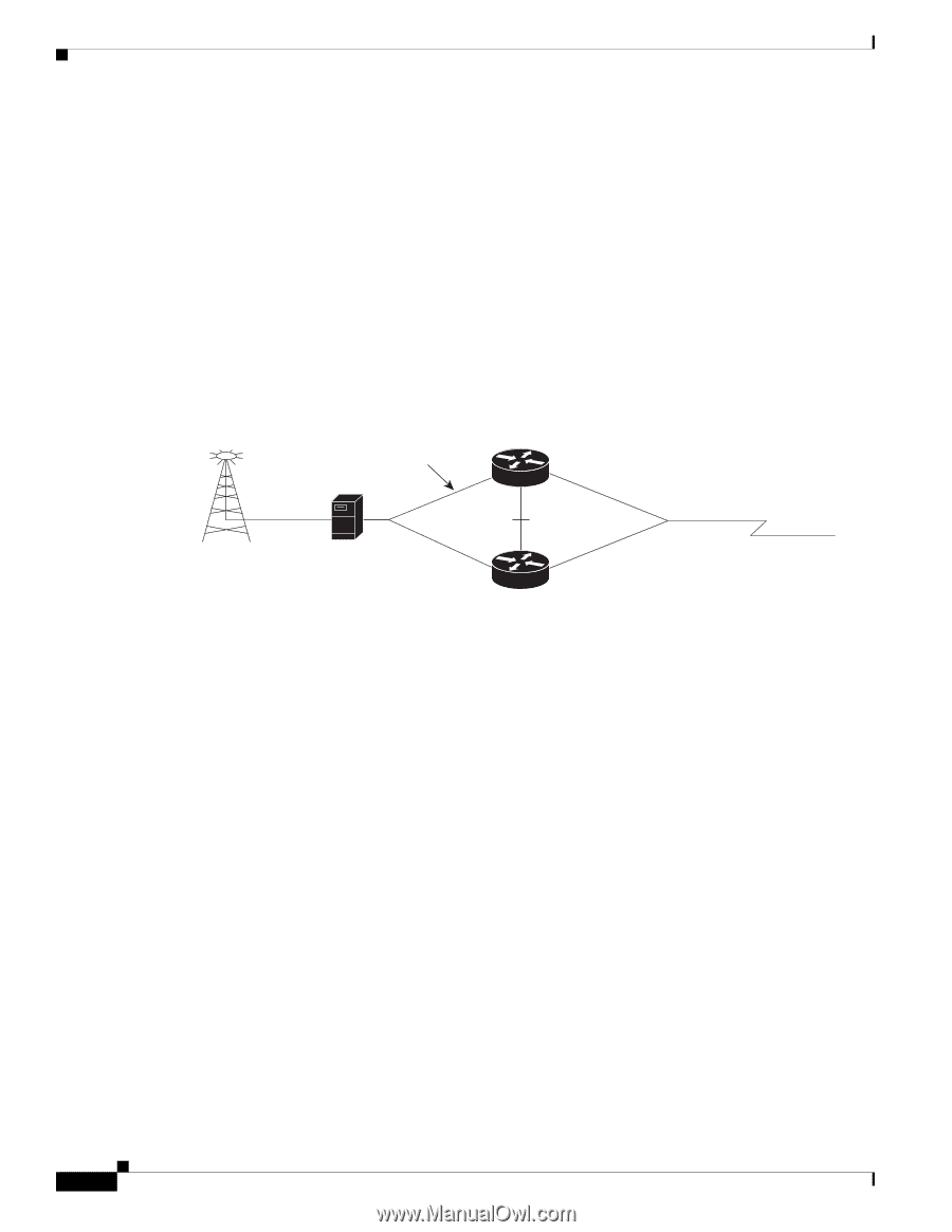
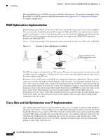
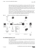
Introduction Chapter 1 Overview of the Cisco 3825 Mobile Wireless Edge Router Division Multiple Access (CDMA) systems is called the Abis interface. The interface between the Node B and RNC in a UMTS system is called the Iub interface (see Appendix B, "Configuration Examples", for sample configurations. RAN-Optimization Implementation In RAN-Optimization (RAN-O), the Cisco 3825 router extends IP connectivity to the cell site and BTS. The router provides bandwidth-efficient IP transport of GSM and UMTS voice and data bearer traffic, as well as maintenance, control, and signaling traffic, over the leased line backhaul network between the BTS and leased line termination and aggregation node via compression (cRTP/cUDP) and packet multiplexing (Multilink PPP). Figure 1-1 shows an example of the placement of and connections for the Cisco 3825 router in RAN-O. Figure 1-1 Example of Cisco 3825 Router in a RAN-O T1/E1 Active T1/E1 backhaul link to IP RAN aggregation node GSM BTS or UMTS Node-B Standby Cisco MWR pair 203231 The BTS site consists of a pair of Cisco 3825 routers. The pair of routers provides an active router and a standby router for redundancy. A failure of the active router causes the standby router to take over as the active router for the BTS site. Each pair of Cisco 3825 routers at the BTS site is identical in hardware configuration. The two routers connect to each other through the Gigabit Ethernet (GE) interfaces. The individual backhaul links to a Cisco 3825 router are cabled from a single T1/E1 termination block in the BTS, connecting to both the active and standby routers by means of a Y cable. The redundancy design to control the active/standby transitions of the router pair leverages Hot Standby Router Protocol (HSRP) to control the relays on the Cisco 2-port T1/E1-RAN interface card, Cisco product number VWIC-2T1/E1-RAN (for more information, see Cisco 2-port T1/E1-RAN Installation Instructions) in each router to ensure that the relays on the active router are closed while the relays on the standby router are open, thus avoiding double termination of the T1 (or E1). Cisco Abis and Iub Optimization over IP Implementation One solution that mobile wireless operators find of value is Cisco's ability to optimize RAN backhaul efficiency (see Figure 1-2). For example, Cisco's GSM Abis Optimization solution increases the T1/E1 bandwidth efficiency by as much as 50%. This means the current traffic loads can be carried using half as many T1/E1 trunks as are presently used. This allows more voice and data calls to be carried over the existing RAN backhaul network, eliminating the need for the operator to add expensive new T1/E1 trunks as traffic demands grow. It will also allow a number of existing trunks to be decommissioned, putting an end to their recurring costs. Cisco 3825 Mobile Wireless Edge Router Software Configuration Guide 1-2 OL-15667-03
-
 1
1 -
2
-
3
-
4
-
5
-
6
-
 7
7 -
 8
8 -
 9
9 -
 10
10 -
 11
11 -
 12
12 -
 13
13 -
 14
14 -
 15
15 -
 16
16 -
 17
17 -
18
-
19
-
20
-
21
-
22
-
23
-
24
-
25
-
26
-
27
-
28
-
29
-
30
-
31
-
32
-
33
-
34
-
35
-
36
-
37
-
38
-
39
-
40
-
41
-
42
-
43
-
44
-
45
-
46
-
47
-
48
-
49
-
50
-
51
-
52
-
53
-
54
-
55
-
56
-
57
-
58
-
59
-
60
-
61
-
62
-
63
-
64
-
65
-
66
-
67
-
68
-
69
-
70
-
71
-
72
-
73
-
74
-
75
-
76
-
77
-
78
-
79
-
80
-
81
-
82
-
83
-
84
-
85
-
86
-
87
-
88
-
89
-
90
-
91
-
92
-
93
-
94
-
95
-
96
-
97
-
98
-
99
-
100
-
101
-
102
-
103
-
104
-
105
-
106
-
107
-
108
-
109
-
110
-
111
-
112
-
113
-
114
-
115
-
116
-
117
-
118
-
119
-
120
-
121
-
122
-
123
-
124
-
125
-
126
-
127
-
128
-
129
-
130
-
131
-
132
-
133
-
134
-
135
-
136
-
137
-
138
-
139
-
140
-
141
-
142
-
143
-
144
-
145
-
146
-
147
-
148
-
149
-
150
-
151
-
152
-
153
-
154
-
155
-
156
-
157
-
158
-
159
-
160
-
161
-
162
-
163
-
164
-
165
-
166
-
167
-
168
-
169
-
170
-
171
-
172
-
173
-
174
-
175
-
176
-
177
-
178
-
179
-
180
-
181
-
182
-
183
-
184
-
185
-
186
-
187
-
188
-
189
-
190
-
191
-
192
-
193
-
194
-
195
-
196
-
197
-
198
-
199
-
200
-
201
-
202
-
203
-
204
-
205
-
206
-
207
-
208
-
209
-
210
-
211
-
212
-
213
-
214
-
215
-
216
-
217
-
218
-
219
-
220
-
221
-
222
-
223
-
224
-
225
-
226
-
227
-
228
-
229
-
230
-
231
-
232
-
233
-
234
-
235
-
236
-
237
-
238
-
239
-
240
-
241
-
242
-
243
-
244
-
245
-
246
-
247
-
248
-
249
-
250
-
251
-
252
-
253
-
254
-
255
-
256
-
257
-
258
-
259
-
260
-
261
-
262
-
263
-
264
-
265
-
266
-
267
-
268
-
269
-
270
-
271
-
272
-
273
-
274
-
275
-
276
-
277
-
278
-
279
-
280
-
281
-
282
-
283
-
284
-
285
-
286
-
287
-
288
-
289
-
290
-
291
-
292
-
293
-
294
-
295
-
296
-
297
-
298
-
299
-
300
-
301
-
302
-
303
-
304
-
305
-
306
-
307
-
308
-
309
-
310
-
311
-
312
-
313
-
314
-
315
-
316
-
317
-
318
-
319
-
320
-
321
-
322
-
323
-
324
-
325
-
326
-
327
-
328
-
329
-
330
-
331
-
332
-
333
-
334
-
335
-
336
-
337
-
338
-
339
-
340
-
341
-
342
-
343
-
344
-
345
-
346
-
347
-
348
-
349
-
350
-
351
-
352
-
353
-
354
-
355
-
356
-
357
-
358
 |
 |