Cisco 3825 Software Configuration Guide - Page 230
Local interface, disable-fallback, preferred-path, MPLS VC labels
 |
UPC - 746320981505
View all Cisco 3825 manuals
Add to My Manuals
Save this manual to your list of manuals |
Page 230 highlights
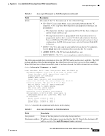
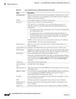
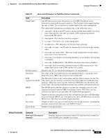
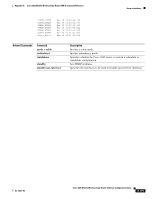
show mpls l2transport vc Appendix A Cisco 3825 Mobile Wireless Edge Router RAN-O Command Reference Table A-5 show mpls l2transport vc Field Descriptions (continued) Field Description Local interface Interface on the local router that has been enabled to send and receive Layer 2 packets. The interface varies, depending on the transport type. The output also shows the status of the interface. VC ID VC identifier assigned to the interface on the router. VC status Status of the VC, which is one of the following: UP-The VC is in a state where it can carry traffic between the two VC endpoints. A VC is up when both imposition and disposition interfaces are programmed. • The disposition interface is programmed if the VC has been configured and the client interface is up. • The imposition interface is programmed if the disposition interface is programmed and a remote VC label and an IGP label exist. The IGP label can be an implicit null in a back-to-back configuration. (An IGP label means there is an LSP to the peer.) DOWN-The VC is not ready to carry traffic between the two VC endpoints. ADMIN DOWN-The VC has been disabled by a user. Output interface Interface on the remote router that has been enabled to transmit and receive Layer 2 packets. imposed label stack Summary of the MPLS label stack used to direct the VC to the PE router. Preferred path Path that was assigned to the VC and the status of that path. The path can be an MPLS traffic engineering tunnel or an IP address or hostname of a PE router. Default path Status of the default path, which can be disabled or active. By default, if the preferred path fails, the router uses the default path. However, you can disable the router from using the default path when the preferred path fails by specifying the disable-fallback keyword with the preferred-path command. Create time Time when the VC was provisioned. last status change Last time the VC state changed. time Signaling protocol Type of protocol used to send the MPLS labels. The output also shows the status of the peer router. MPLS VC labels Local VC label is a disposition label, which determines the egress interface of an arriving packet from the MPLS backbone. The remote VC label is a disposition VC label of the remote peer router. Group ID Local group ID is used to group VCs locally. The remote group ID is used by the peer to group several VCs. MTU Maximum transmission unit specified for the local and remote interfaces. Remote interface description Interface on the remote router that has been enabled to transmit and receive Layer 2 packets. Sequencing Indicates whether sequencing of out-of-order packets is enabled or disabled. A-98 Cisco 3825 Mobile Wireless Edge Router Software Configuration Guide OL-15667-03
-
 1
1 -
2
-
3
-
4
-
5
-
6
-
7
-
8
-
9
-
10
-
11
-
12
-
13
-
14
-
15
-
16
-
17
-
18
-
19
-
20
-
21
-
22
-
23
-
24
-
25
-
26
-
27
-
28
-
29
-
30
-
31
-
32
-
33
-
34
-
35
-
36
-
37
-
38
-
39
-
40
-
41
-
42
-
43
-
44
-
45
-
46
-
47
-
48
-
49
-
50
-
51
-
52
-
53
-
54
-
55
-
56
-
57
-
58
-
59
-
60
-
61
-
62
-
63
-
64
-
65
-
66
-
67
-
68
-
69
-
70
-
71
-
72
-
73
-
74
-
75
-
76
-
77
-
78
-
79
-
80
-
81
-
82
-
83
-
84
-
85
-
86
-
87
-
88
-
89
-
90
-
91
-
92
-
93
-
94
-
95
-
96
-
97
-
98
-
99
-
100
-
101
-
102
-
103
-
104
-
105
-
106
-
107
-
108
-
109
-
110
-
111
-
112
-
113
-
114
-
115
-
116
-
117
-
118
-
119
-
120
-
121
-
122
-
123
-
124
-
125
-
126
-
127
-
128
-
129
-
130
-
131
-
132
-
133
-
134
-
135
-
136
-
137
-
138
-
139
-
140
-
141
-
142
-
143
-
144
-
145
-
146
-
147
-
148
-
149
-
150
-
151
-
152
-
153
-
154
-
155
-
156
-
157
-
158
-
159
-
160
-
161
-
162
-
163
-
164
-
165
-
166
-
167
-
168
-
169
-
170
-
171
-
172
-
173
-
174
-
175
-
176
-
177
-
178
-
179
-
180
-
181
-
182
-
183
-
184
-
185
-
186
-
187
-
188
-
189
-
190
-
191
-
192
-
193
-
194
-
195
-
196
-
197
-
198
-
199
-
200
-
201
-
202
-
203
-
204
-
205
-
206
-
207
-
208
-
209
-
210
-
211
-
212
-
213
-
214
-
215
-
216
-
217
-
218
-
219
-
220
-
221
-
222
-
223
-
224
-
 225
225 -
 226
226 -
 227
227 -
 228
228 -
 229
229 -
 230
230 -
 231
231 -
 232
232 -
 233
233 -
 234
234 -
 235
235 -
236
-
237
-
238
-
239
-
240
-
241
-
242
-
243
-
244
-
245
-
246
-
247
-
248
-
249
-
250
-
251
-
252
-
253
-
254
-
255
-
256
-
257
-
258
-
259
-
260
-
261
-
262
-
263
-
264
-
265
-
266
-
267
-
268
-
269
-
270
-
271
-
272
-
273
-
274
-
275
-
276
-
277
-
278
-
279
-
280
-
281
-
282
-
283
-
284
-
285
-
286
-
287
-
288
-
289
-
290
-
291
-
292
-
293
-
294
-
295
-
296
-
297
-
298
-
299
-
300
-
301
-
302
-
303
-
304
-
305
-
306
-
307
-
308
-
309
-
310
-
311
-
312
-
313
-
314
-
315
-
316
-
317
-
318
-
319
-
320
-
321
-
322
-
323
-
324
-
325
-
326
-
327
-
328
-
329
-
330
-
331
-
332
-
333
-
334
-
335
-
336
-
337
-
338
-
339
-
340
-
341
-
342
-
343
-
344
-
345
-
346
-
347
-
348
-
349
-
350
-
351
-
352
-
353
-
354
-
355
-
356
-
357
-
358
 |
 |