Cisco 3825 Software Configuration Guide - Page 33
Ethernet over MPLS, VLAN Mode, Port Mode - vlan config
 |
UPC - 746320981505
View all Cisco 3825 manuals
Add to My Manuals
Save this manual to your list of manuals |
Page 33 highlights
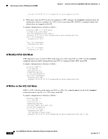
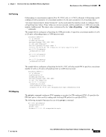
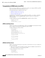
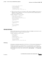
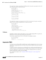
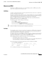
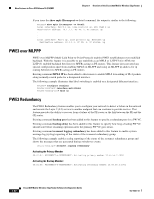
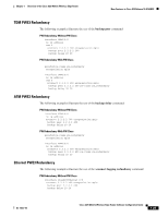
Chapter 1 Overview of the Cisco 3825 Mobile Wireless Edge Router New Features in Cisco IOS Release 12.4(16)MR1 Ethernet over MPLS The Ethernet over MPLS feature allows you to transport Ethernet traffic over MPLS networks. This feature can be configured in the following two ways: VLAN Mode A VLAN is a switched network that is logically segmented by functions, project teams, or applications regardless of the physical location of users. To connect two VLAN networks in different locations, configure the PE routers at each end of the MPLS backbone and add a point-to-point virtual connection (VC). Only two PE routers at the ingress and egress points of the MPLS backbone have dedicated VCs to transport Layer 2 VLAN traffic. Ethernet over MPLS in VLAN mode transports Ethernet traffic from a source 802.1Q VLAN to a destination 802.1Q VLAN over a core MPLS network. The following example configures Ethernet in VLAN mode: Router> enable Router# configure terminal Router(config)# interface gigabitethernet 0/0.1 Router(config-subif)# encapsulation dot1q 100 Router(config-subif)# xconnect 10.0.0.1 123 encapsulation mpls Note Ethernet over MPLS in VLAN mode must be configured on subinterfaces. Port Mode Port mode allows a frame coming into an interface to be packed into an MPLS packet and transported over the MPLS backbone to an egress interface. The entire Ethernet frame without the preamble or a frame check sequence (FCS) is transported as a single packet. To configure in port mode, use the xconnect command in the interface configuration mode and specify the destination address and the VC ID. The syntax of the xconnect command is the same for all other transport types. Each interface is associated with one unique PW VC label. When configuring Ethernet over MPLS in port mode, use the following guidelines: - The pseudowire (PW) VC type is set to Ethernet. - Port mode and Ethernet VLAN mode are mutually exclusive. If you enable a main interface for port-to-port transport, you cannot also enter commands on a subinterface. The command output in the following example shows two VCs for Ethernet over MPLS: Router# show mpls l2transport vc Local intf Local circuit Dest address VC ID Status Fa0/0.1 Eth VLAN 2 10.1.1.1 2 UP Fa0/1 Ethernet 10.1.1.1 8 UP VC 2 is in Ethernet VLAN mode. VC 8 is in Ethernet port mode. OL-15667-03 Cisco 3825 Mobile Wireless Edge Router Software Configuration Guide 1-23
-
 1
1 -
2
-
3
-
4
-
5
-
6
-
7
-
8
-
9
-
10
-
11
-
12
-
13
-
14
-
15
-
16
-
17
-
18
-
19
-
20
-
21
-
22
-
23
-
24
-
25
-
26
-
27
-
 28
28 -
 29
29 -
 30
30 -
 31
31 -
 32
32 -
 33
33 -
 34
34 -
 35
35 -
 36
36 -
 37
37 -
 38
38 -
39
-
40
-
41
-
42
-
43
-
44
-
45
-
46
-
47
-
48
-
49
-
50
-
51
-
52
-
53
-
54
-
55
-
56
-
57
-
58
-
59
-
60
-
61
-
62
-
63
-
64
-
65
-
66
-
67
-
68
-
69
-
70
-
71
-
72
-
73
-
74
-
75
-
76
-
77
-
78
-
79
-
80
-
81
-
82
-
83
-
84
-
85
-
86
-
87
-
88
-
89
-
90
-
91
-
92
-
93
-
94
-
95
-
96
-
97
-
98
-
99
-
100
-
101
-
102
-
103
-
104
-
105
-
106
-
107
-
108
-
109
-
110
-
111
-
112
-
113
-
114
-
115
-
116
-
117
-
118
-
119
-
120
-
121
-
122
-
123
-
124
-
125
-
126
-
127
-
128
-
129
-
130
-
131
-
132
-
133
-
134
-
135
-
136
-
137
-
138
-
139
-
140
-
141
-
142
-
143
-
144
-
145
-
146
-
147
-
148
-
149
-
150
-
151
-
152
-
153
-
154
-
155
-
156
-
157
-
158
-
159
-
160
-
161
-
162
-
163
-
164
-
165
-
166
-
167
-
168
-
169
-
170
-
171
-
172
-
173
-
174
-
175
-
176
-
177
-
178
-
179
-
180
-
181
-
182
-
183
-
184
-
185
-
186
-
187
-
188
-
189
-
190
-
191
-
192
-
193
-
194
-
195
-
196
-
197
-
198
-
199
-
200
-
201
-
202
-
203
-
204
-
205
-
206
-
207
-
208
-
209
-
210
-
211
-
212
-
213
-
214
-
215
-
216
-
217
-
218
-
219
-
220
-
221
-
222
-
223
-
224
-
225
-
226
-
227
-
228
-
229
-
230
-
231
-
232
-
233
-
234
-
235
-
236
-
237
-
238
-
239
-
240
-
241
-
242
-
243
-
244
-
245
-
246
-
247
-
248
-
249
-
250
-
251
-
252
-
253
-
254
-
255
-
256
-
257
-
258
-
259
-
260
-
261
-
262
-
263
-
264
-
265
-
266
-
267
-
268
-
269
-
270
-
271
-
272
-
273
-
274
-
275
-
276
-
277
-
278
-
279
-
280
-
281
-
282
-
283
-
284
-
285
-
286
-
287
-
288
-
289
-
290
-
291
-
292
-
293
-
294
-
295
-
296
-
297
-
298
-
299
-
300
-
301
-
302
-
303
-
304
-
305
-
306
-
307
-
308
-
309
-
310
-
311
-
312
-
313
-
314
-
315
-
316
-
317
-
318
-
319
-
320
-
321
-
322
-
323
-
324
-
325
-
326
-
327
-
328
-
329
-
330
-
331
-
332
-
333
-
334
-
335
-
336
-
337
-
338
-
339
-
340
-
341
-
342
-
343
-
344
-
345
-
346
-
347
-
348
-
349
-
350
-
351
-
352
-
353
-
354
-
355
-
356
-
357
-
358
 |
 |