Cisco 3825 Software Configuration Guide - Page 53
Setup Command Facility, Before Starting Your Router - console port
 |
UPC - 746320981505
View all Cisco 3825 manuals
Add to My Manuals
Save this manual to your list of manuals |
Page 53 highlights
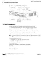
Chapter 3 First-Time Configuration Setup Command Facility Interface (port) numbers begin at logical 0 for each interface type; ports are numbered from right to left. • The two built-in Gigabit Ethernet 10/100/1000 logical interfaces are GE 0/0 and GE 0/1. • The logical slot number for all Cisco 2-port T1/E1-RAN interfaces in the built-in Cisco 2-port T1/E1-RAN interface card slot is always 0. (The HWIC0, HWIC1, HWIC2, and HWIC3 slot designations are for physical slot identification only.) Interfaces in the Cisco 2-port T1/E1-RAN interface cards are numbered from right to left, starting with logical 0/0/0 for each interface type, regardless of the physical slot in which the Cisco 2-port T1/E1-RAN interface cards are installed. For example, if you have a Cisco 2-port T1/E1-RAN interface card in two of the 2-port T1/E1-RAN interface card slots (physical slots HWIC0 and HWIC1), then the logical interfaces are: - Serial 0/0/0 and Serial 0/0/1 in physical slot HWIC0 - Serial 0/1/0 and Serial 0/1/1 in physical slot HWIC1 However, if you install a Cisco 2-port T1/E1-RAN interface card in physical slot HWIC1 (leaving slot HWIC0 empty), the logical interfaces in slot HWIC1 are Serial 0/0/0 and Serial 0/0/1. If you later add a Cisco 2-port T1/E1-RAN interface card to slot HWIC0, the interface numbering will shift. The configuration that you created for logical interfaces Serial 0/0/0 and Serial 0/0/1 will now be applied to the Cisco 2-port T1/E1-RAN interface card in slot HWIC0, and you will need to create a new configuration for the interfaces that you previously configured on HWIC1 (which will now be Serial 0/1/0 and Serial 0/1/1). • The slot number of the Cisco 2-port T1/E1-RAN interfaces installed in slot 1 using an NM-2W network module is always logical 1, and the interfaces are always numbered from the right to left. Setup Command Facility The setup command facility prompts you for information that is needed to start a router functioning quickly. The facility steps you through a basic configuration, including LAN interfaces. If you prefer to configure the router manually or if you wish to configure a module or interface that is not included in the setup command facility, proceed to "Chapter 2, "Cisco IOS Software Basics" to familiarize yourself with the command-line interface (CLI) and then proceed to Chapter 4, "Configuring the Cisco 3825 Mobile Wireless Edge Router in a RAN-O Solution with the Command-Line Interface" for instructions on configuring your Cisco 3825 router. Before Starting Your Router Before you power on your router and begin using the setup command facility, follow these steps: Step 1 Step 2 Set up the hardware and connect the console and network cables as described in the "Connecting Cables to Cisco 3800 Series Routers" section of the Cisco 3800 Series Hardware Installation guide. Configure your PC terminal emulation program for 9600 baud, 8 data bits, no parity, and 1 stop bit. OL-15667-03 Cisco 3825 Mobile Wireless Edge Router Software Configuration Guide 3-3
-
 1
1 -
2
-
3
-
4
-
5
-
6
-
7
-
8
-
9
-
10
-
11
-
12
-
13
-
14
-
15
-
16
-
17
-
18
-
19
-
20
-
21
-
22
-
23
-
24
-
25
-
26
-
27
-
28
-
29
-
30
-
31
-
32
-
33
-
34
-
35
-
36
-
37
-
38
-
39
-
40
-
41
-
42
-
43
-
44
-
45
-
46
-
47
-
 48
48 -
 49
49 -
 50
50 -
 51
51 -
 52
52 -
 53
53 -
 54
54 -
 55
55 -
 56
56 -
 57
57 -
 58
58 -
59
-
60
-
61
-
62
-
63
-
64
-
65
-
66
-
67
-
68
-
69
-
70
-
71
-
72
-
73
-
74
-
75
-
76
-
77
-
78
-
79
-
80
-
81
-
82
-
83
-
84
-
85
-
86
-
87
-
88
-
89
-
90
-
91
-
92
-
93
-
94
-
95
-
96
-
97
-
98
-
99
-
100
-
101
-
102
-
103
-
104
-
105
-
106
-
107
-
108
-
109
-
110
-
111
-
112
-
113
-
114
-
115
-
116
-
117
-
118
-
119
-
120
-
121
-
122
-
123
-
124
-
125
-
126
-
127
-
128
-
129
-
130
-
131
-
132
-
133
-
134
-
135
-
136
-
137
-
138
-
139
-
140
-
141
-
142
-
143
-
144
-
145
-
146
-
147
-
148
-
149
-
150
-
151
-
152
-
153
-
154
-
155
-
156
-
157
-
158
-
159
-
160
-
161
-
162
-
163
-
164
-
165
-
166
-
167
-
168
-
169
-
170
-
171
-
172
-
173
-
174
-
175
-
176
-
177
-
178
-
179
-
180
-
181
-
182
-
183
-
184
-
185
-
186
-
187
-
188
-
189
-
190
-
191
-
192
-
193
-
194
-
195
-
196
-
197
-
198
-
199
-
200
-
201
-
202
-
203
-
204
-
205
-
206
-
207
-
208
-
209
-
210
-
211
-
212
-
213
-
214
-
215
-
216
-
217
-
218
-
219
-
220
-
221
-
222
-
223
-
224
-
225
-
226
-
227
-
228
-
229
-
230
-
231
-
232
-
233
-
234
-
235
-
236
-
237
-
238
-
239
-
240
-
241
-
242
-
243
-
244
-
245
-
246
-
247
-
248
-
249
-
250
-
251
-
252
-
253
-
254
-
255
-
256
-
257
-
258
-
259
-
260
-
261
-
262
-
263
-
264
-
265
-
266
-
267
-
268
-
269
-
270
-
271
-
272
-
273
-
274
-
275
-
276
-
277
-
278
-
279
-
280
-
281
-
282
-
283
-
284
-
285
-
286
-
287
-
288
-
289
-
290
-
291
-
292
-
293
-
294
-
295
-
296
-
297
-
298
-
299
-
300
-
301
-
302
-
303
-
304
-
305
-
306
-
307
-
308
-
309
-
310
-
311
-
312
-
313
-
314
-
315
-
316
-
317
-
318
-
319
-
320
-
321
-
322
-
323
-
324
-
325
-
326
-
327
-
328
-
329
-
330
-
331
-
332
-
333
-
334
-
335
-
336
-
337
-
338
-
339
-
340
-
341
-
342
-
343
-
344
-
345
-
346
-
347
-
348
-
349
-
350
-
351
-
352
-
353
-
354
-
355
-
356
-
357
-
358
 |
 |