Cisco 5508 Installation Guide
Cisco 5508 - Wireless Controller - Network Management Device Manual
 |
UPC - 882658250057
View all Cisco 5508 manuals
Add to My Manuals
Save this manual to your list of manuals |
Cisco 5508 manual content summary:
- Cisco 5508 | Installation Guide - Page 1
Cisco 5500 Series Wireless Controller Installation Guide This guide is designed to help you install and minimally configure your Cisco 5500 Series Wireless Controller. • Compliance and Safety Information, page 1 • Controller Overview, page 3 • Unpacking and Installing the Controller, page 8 • Using - Cisco 5508 | Installation Guide - Page 2
of a suitably installed ground conductor. Contact the appropriate electrical inspection authority or an electrician if you are uncertain that suitable grounding is available. Statement 1024 Statement 371-Power Cable and AC Adapter Cisco 5500 Series Wireless Controller Installation Guide 2 78 - Cisco 5508 | Installation Guide - Page 3
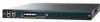
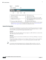
access points as they appear on the network, it is not necessary to have any access points on the network in order to install and configure a controller. Figure 1 shows the front panel of the Cisco 5508 Wireless Controller. 78-18998-01 Cisco 5500 Series Wireless Controller Installation Guide - Cisco 5508 | Installation Guide - Page 4
the console port. If it is not installed, prompts guide you through a simple installation process. Note For information about downloading the latest Cisco Windows USB Console Driver, refer to the Release Notes for Cisco Wireless LAN Controllers and Lightweight Access Points for Release 6.0. Cisco - Cisco 5508 | Installation Guide - Page 5
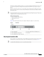
the front panel of the unit. You can use the LED indications to quickly assess the unit's status. The LED indicators are described in Table 1. Note An amber LED could indicate an error or a possible hardware failure. 78-18998-01 Cisco 5500 Series Wireless Controller Installation Guide 5 - Cisco 5508 | Installation Guide - Page 6
the standby power supply fan is not spinning or that the power supply is over temperature. Continuous amber: Indicates that the power supply is in failure condition. Note When the PS1 or PS2 LED is amber, the power supply shuts down. Cisco 5500 Series Wireless Controller Installation Guide 6 78 - Cisco 5508 | Installation Guide - Page 7
SYS blinks amber. • ALM is continuous amber. Temperature Error: • SYS is off. • ALM blinks amber. Note Check for blocked air vents and fans on the controller, and make sure that ambient room temperature is below 104° F (40° C). 78-18998-01 Cisco 5500 Series Wireless Controller Installation Guide 7 - Cisco 5508 | Installation Guide - Page 8
in order to install the controller: • Wireless LAN controller hardware - Controller with factory-supplied power cord and mounting hardware - Network, operating system service network, and access point cables as required • Command-line interface (CLI) console - VT-100 terminal emulator on CLI console - Cisco 5508 | Installation Guide - Page 9
port, and secret (if you are configuring a RADIUS server). • The country code for this installation. Refer to the Cisco Wireless LAN Controller Configuration Guide for country code information. This guide is available at cisco.com. • Status of the 802.11a, 802.11b, 802.11g, and 802.11n networks - Cisco 5508 | Installation Guide - Page 10
connection to a network through a 1300 nM (LX/LH) fiber-optic link using an LC physical connector. The 1000BASE-T SFP modules provide a 1000-Mb/s wired connection to a network through a copper link using an RJ-45 physical connector. Cisco 5500 Series Wireless Controller Installation Guide 10 78 - Cisco 5508 | Installation Guide - Page 11
the Controller on a Desktop or Shelf, page 12 • Installing the Controller in a 4-Post Rack, page 12 • Installing the Controller in a 2-Post Rack-Flush Mount, page 16 • Installing the Controller in a 2-Post Rack-Mid-Mount, page 18 78-18998-01 Cisco 5500 Series Wireless Controller Installation Guide - Cisco 5508 | Installation Guide - Page 12
right). Figure 4 Installing the Front Brackets RP SP USB0 USB1 CONSOLE EN EN Cisco 5500 Series Wireless Controller 12 34 56 78 Model 5508 PS1 PS2 SYS ACT 1 Front bracket 12 2 M4x0.7 x 8mm flat head screws 251200 Cisco 5500 Series Wireless Controller Installation Guide 12 78-18998-01 - Cisco 5508 | Installation Guide - Page 13
Figure 6 Installing the Controller in the Rack (Front) RP SP USB0 USB1 CONSOLE EN EN Cisco 5500 Series Wireless Controller 12 34 56 78 Model 5508 PS1 PS2 SYS ACT 251202 Step 4 Measure the distance between the front and rear rack rails and select the proper slide-mount brackets: Note The - Cisco 5508 | Installation Guide - Page 14
SP USB0 USB1 CONSOLE EN EN Cisco 5500 Series Wireless Controller 12 34 56 78 Model 5508 PS1 PS2 SYS ACT RP SP USB0 USB1 CONSOLE EN EN Cisco 5500 Series Wireless Controller 12 34 56 78 Model 5508 PS1 PS2 SYS ACT 251237 Cisco 5500 Series Wireless Controller Installation Guide 14 78 - Cisco 5508 | Installation Guide - Page 15
SP USB0 USB1 CONSOLE EN EN Cisco 5500 Series Wireless Controller 12 34 56 78 Model 5508 PS1 PS2 SYS ACT 251238 RP SP USB0 USB1 CONSOLE EN EN Cisco 5500 Series Wireless Controller 12 34 56 78 Model 5508 PS1 PS2 SYS ACT Step 5 Step 6 Install the proper slide-mount brackets into the - Cisco 5508 | Installation Guide - Page 16
and the other devices installed in the rack. Figure 11 Installing the Cable Guide RP SP USB0 USB1 CONSOLE EN EN Cisco 5500 Series Wireless Controller 12 34 56 78 Model 5508 PS1 PS2 SYS ACT 251240 Installing the Controller in a 2-Post Rack-Flush Mount Caution The controller weighs 20 lbs - Cisco 5508 | Installation Guide - Page 17
12 Installing the Front Brackets Unpacking and Installing the Controller RP SP USB0 USB1 CONSOLE EN EN Cisco 5500 Series Wireless Controller 12 34 56 78 Model 5508 PS1 PS2 SYS ACT 12 251200 1 Front bracket 2 M4x0.7 x 8mm flat head screws Step 2 Mount the front of the controller - Cisco 5508 | Installation Guide - Page 18
Unpacking and Installing the Controller Figure 14 Installing the Cable Guide RP SP USB0 USB1 CONSOLE EN EN Cisco 5500 Series Wireless Controller 12 34 56 78 Model 5508 PS1 PS2 SYS ACT 205855 Installing the Controller in a 2-Post Rack-Mid-Mount Caution The controller weighs 20 lbs (9.1 - Cisco 5508 | Installation Guide - Page 19
on the rack rail thread type (see Figure 16). Figure 16 Installing the Controller in the Rack RP SP USB0 USB1 CONSOLE EN EN Cisco 5500 Series Wireless Controller 12 34 56 78 Model 5508 PS1 PS2 SYS ACT 205854 78-18998-01 Cisco 5500 Series Wireless Controller Installation Guide 19 - Cisco 5508 | Installation Guide - Page 20
must be grounded. The receptacles of the AC power cables used to provide power to the chassis must be the grounding type, and the grounding conductors should connect to protective earth ground at the service equipment. Cisco 5500 Series Wireless Controller Installation Guide 20 78-18998-01 - Cisco 5508 | Installation Guide - Page 21
measurement should be between 1 and 10 megohms (Mohms). Figure 18 ESD Wrist Strap Connector Location RP SP USB0 USB1 CONSOLE EN EN Cisco 5500 Series Wireless Controller 12 34 56 78 Model 5508 PS1 PS2 SYS ACT 251239 78-18998-01 Cisco 5500 Series Wireless Controller Installation Guide 21 - Cisco 5508 | Installation Guide - Page 22
Step 1 Step 2 Step 3 Plug an AC power cord into the back of the controller and connect the other end to a grounded 100 to 240 VAC, 50/60 Hz electrical outlet. Turn on the power supply. Observe the bootup on the CLI screen. Cisco 5500 Series Wireless Controller Installation Guide 22 78-18998-01 - Cisco 5508 | Installation Guide - Page 23
Cisco Systems, Inc. All rights reserved. Cisco AireOS Version 6.0.100.1 Initializing OS Services: ok . . . Starting SSHPM LSC PROV LIST: ok Starting Management Services: Web Server: ok CLI: ok Secure Web: ok License Agent: ok 78-18998-01 Cisco 5500 Series Wireless Controller Installation Guide - Cisco 5508 | Installation Guide - Page 24
or disable link aggregation (LAG) by choosing yes or no. Enter the IP address, netmask, default router IP address, and optional VLAN identifier (a valid VLAN identifier or 0 for an untagged VLAN) for the management interface. Cisco 5500 Series Wireless Controller Installation Guide 24 78-18998-01 - Cisco 5508 | Installation Guide - Page 25
the switch interface configuration. Step 8 Enter the IP address of the default DHCP server that will supply IP addresses to clients, the controller's management interface, and optionally the service-port interface. Note The management interface is the default interface for in-band management of the - Cisco 5508 | Installation Guide - Page 26
Cisco Aironet lightweight access points do not connect to the Cisco 5500 Series Wireless Controller if the date and time are not set properly. Set the current date and time on the controller before allowing the access points to connect to it. Cisco 5500 Series Wireless Controller Installation Guide - Cisco 5508 | Installation Guide - Page 27
-45 physical connector. Depending on the distribution system physical port to be assigned, use Ethernet Category 5 or higher cables or SX/LX/LH compatible fiber-optic cables to connect the network equipment to the controller. 78-18998-01 Cisco 5500 Series Wireless Controller Installation Guide 27 - Cisco 5508 | Installation Guide - Page 28
to the Cisco Wireless LAN Controller Configuration Guide, Release 6.0, for information on configuring the controller to meet the specific needs of your wireless network. Installing a Power Supply Unit The controller can be powered using one or two power supply units. When the controller is equipped - Cisco 5508 | Installation Guide - Page 29
tighten the captive screw. Do not overtighten. Plug the power cord into the power supply unit and the other end into a grounded 100 to 240 VAC 50/60 Hz electrical outlet. Make sure that both power supply units are turned on. 78-18998-01 Cisco 5500 Series Wireless Controller Installation Guide 29 - Cisco 5508 | Installation Guide - Page 30
: Step 1 Step 2 Slide the fan assembly into the chassis until the two captive installation screws make contact with the chassis. Using a screwdriver, tighten the two captive installation screws by turning them clockwise. Cisco 5500 Series Wireless Controller Installation Guide 30 78-18998-01 - Cisco 5508 | Installation Guide - Page 31
Click Go. The Cisco Limited Warranty and Software License page from the Information Packet appears. d. Read the document online, or click the PDF icon to download and print the document in Adobe Portable Document Format (PDF). 78-18998-01 Cisco 5500 Series Wireless Controller Installation Guide 31 - Cisco 5508 | Installation Guide - Page 32
contact your Cisco Sales and Service Representative. Complete the information below, and keep it for reference: Company product purchased from Company telephone number Product model number Product serial number Maintenance contract number Cisco 5500 Series Wireless Controller Installation Guide 32 - Cisco 5508 | Installation Guide - Page 33
. The use of the word partner does not imply a partnership relationship between Cisco and any other company. (0812R) Copyright © 2009, Cisco Systems, Inc. All rights reserved. © 2009 Cisco Systems, Inc. All rights reserved. 78-18998-01 Cisco 5500 Series Wireless Controller Installation Guide 33 - Cisco 5508 | Installation Guide - Page 34
Cisco 90-Day Limited Hardware Warranty Terms Cisco 5500 Series Wireless Controller Installation Guide 34 78-18998-01
-
 1
1 -
 2
2 -
 3
3 -
 4
4 -
 5
5 -
 6
6 -
 7
7 -
8
-
9
-
10
-
11
-
12
-
13
-
14
-
15
-
16
-
17
-
18
-
19
-
20
-
21
-
22
-
23
-
24
-
25
-
26
-
27
-
28
-
29
-
30
-
31
-
32
-
33
-
34
 |
 |

Americas Headquarters:
Cisco Systems, Inc., 170 West Tasman Drive, San Jose, CA 95134-1706
USA
Cisco 5500 Series Wireless Controller
Installation Guide
This guide is designed to help you install and minimally configure your Cisco 5500 Series Wireless
Controller.
•
Compliance and Safety Information, page 1
•
Controller Overview, page 3
•
Unpacking and Installing the Controller, page 8
•
Using the Startup Wizard, page 24
•
Controller Specifications, page 31
•
Obtaining Documentation and Submitting a Service Request, page 31
•
Cisco 90-Day Limited Hardware Warranty Terms, page 31
Compliance and Safety Information
FCC Safety Compliance Statement
Modifying the equipment without Cisco’s authorization may result in the equipment no longer
complying with FCC requirements for Class A digital devices. In that event, your right to use the
equipment may be limited by FCC regulations, and you may be required to correct any interference to
radio or television communications at your own expense.