Cisco 6941 Administration Guide - Page 178
E-5, Attaching the Cables, Step 5
 |
UPC - 882658277801
View all Cisco 6941 manuals
Add to My Manuals
Save this manual to your list of manuals |
Page 178 highlights
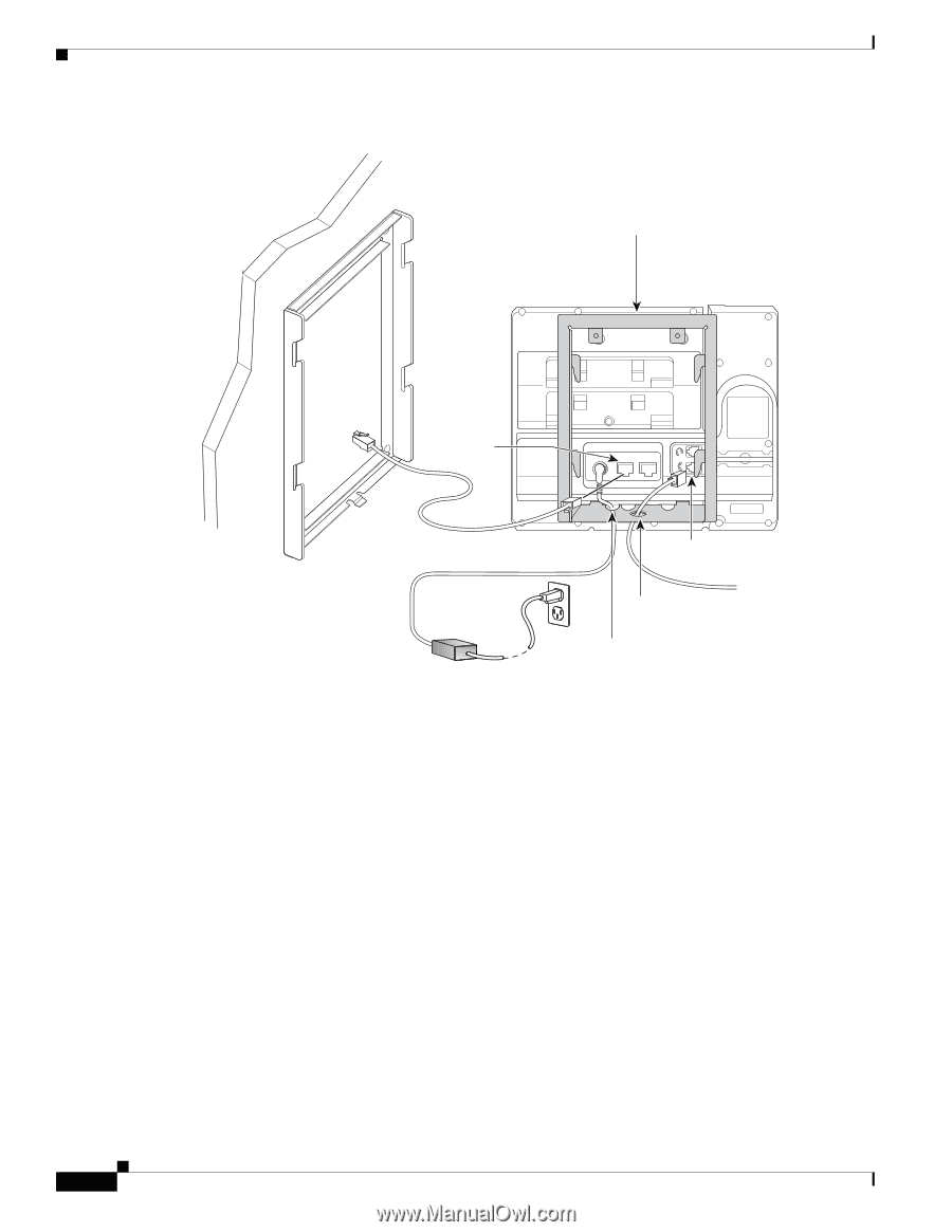
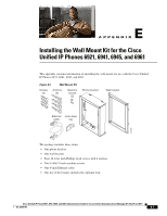
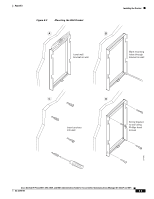
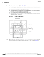
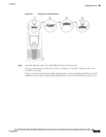
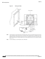
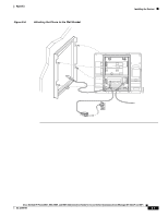
Installing the Bracket Figure E-5 Attaching the Cables Wall bracket Appendix Phone bracket Network port 274939 Handset port AC adapter port (optional power cable) Phone bracket cable access hole U-shaped holes for cables Step 5 Step 6 Attach the phone to the wall bracket by inserting the tabs on the top of the phone bracket into the slots on the wall bracket. Ensure that the power cord and any other cable that does not terminate in the wall behind the bracket are positioned in one of the cable-access openings in the bottom of the bracket. The phone and wall brackets' openings together form circular openings with room for one cable per opening (Figure E-6). Use the locking key to lock the phone to the wall bracket. Cisco Unified IP Phone 6921, 6941, 6945, and 6961 Administration Guide for Cisco Unified Communications Manager 8.5 (SCCP and SIP) E-6 OL-23769-01
-
 1
1 -
2
-
3
-
4
-
5
-
6
-
7
-
8
-
9
-
10
-
11
-
12
-
13
-
14
-
15
-
16
-
17
-
18
-
19
-
20
-
21
-
22
-
23
-
24
-
25
-
26
-
27
-
28
-
29
-
30
-
31
-
32
-
33
-
34
-
35
-
36
-
37
-
38
-
39
-
40
-
41
-
42
-
43
-
44
-
45
-
46
-
47
-
48
-
49
-
50
-
51
-
52
-
53
-
54
-
55
-
56
-
57
-
58
-
59
-
60
-
61
-
62
-
63
-
64
-
65
-
66
-
67
-
68
-
69
-
70
-
71
-
72
-
73
-
74
-
75
-
76
-
77
-
78
-
79
-
80
-
81
-
82
-
83
-
84
-
85
-
86
-
87
-
88
-
89
-
90
-
91
-
92
-
93
-
94
-
95
-
96
-
97
-
98
-
99
-
100
-
101
-
102
-
103
-
104
-
105
-
106
-
107
-
108
-
109
-
110
-
111
-
112
-
113
-
114
-
115
-
116
-
117
-
118
-
119
-
120
-
121
-
122
-
123
-
124
-
125
-
126
-
127
-
128
-
129
-
130
-
131
-
132
-
133
-
134
-
135
-
136
-
137
-
138
-
139
-
140
-
141
-
142
-
143
-
144
-
145
-
146
-
147
-
148
-
149
-
150
-
151
-
152
-
153
-
154
-
155
-
156
-
157
-
158
-
159
-
160
-
161
-
162
-
163
-
164
-
165
-
166
-
167
-
168
-
169
-
170
-
171
-
172
-
 173
173 -
 174
174 -
 175
175 -
 176
176 -
 177
177 -
 178
178 -
 179
179 -
 180
180 -
 181
181 -
 182
182 -
 183
183 -
184
-
185
-
186
-
187
-
188
-
189
-
190
-
191
-
192
-
193
-
194
-
195
-
196
 |
 |