Cisco 8540 User Guide
Cisco 8540 - Catalyst Campus Switch Router Modular Expansion Base Manual
 |
View all Cisco 8540 manuals
Add to My Manuals
Save this manual to your list of manuals |
Cisco 8540 manual content summary:
- Cisco 8540 | User Guide - Page 1
Notes S/W Config Online Help 6 I access this information through: % Printed docs 7 Which method do you prefer? % Cisco Connection Online (CCO) % Other: % CD-ROM 8 I use the following three product features the most: Document Information Document Title: Catalyst 8540 Chassis Installation Guide - Cisco 8540 | User Guide - Page 2
NO POSTAGE NECESSARY IF MAILED IN THE UNITED STATES BUSINESS REPLY MAIL FIRST-CLASS MAIL PERMIT NO. 4631 SAN JOSE CA POSTAGE WILL BE PAID BY ADDRESSEE ATTN DOCUMENT RESOURCE CONNECTION CISCO SYSTEMS INC 170 WEST TASMAN DRIVE SAN JOSE CA 95134-9883 - Cisco 8540 | User Guide - Page 3
Catalyst 8540 Chassis Installation Guide Corporate Headquarters Cisco Systems, Inc. 170 West Tasman Drive San Jose, CA 95134-1706 USA http://www.cisco.com Tel: 408 526-4000 800 553-NETS (6387) Fax: 408 526-4100 Customer Order Number: DOC-786134= Text Part Number: 78-6134-03 - Cisco 8540 | User Guide - Page 4
. IF YOU ARE UNABLE TO LOCATE THE SOFTWARE LICENSE OR LIMITED WARRANTY, CONTACT YOUR CISCO REPRESENTATIVE FOR A COPY. The following information is for in this manual generates and may radiate radio-frequency energy. If it is not installed in accordance with Cisco's installation instructions, it - Cisco 8540 | User Guide - Page 5
mentioned in this document are the property of their respective owners. The use of the word partner does not imply a partnership relationship between Cisco and any of its resellers. (9912R) Catalyst 8540 Chassis Installation Guide Copyright © 1998-2000, Cisco Systems, Inc. All rights reserved. - Cisco 8540 | User Guide - Page 6
- Cisco 8540 | User Guide - Page 7
xiv Cisco Connection Online xiv Technical Assistance Center xv Documentation Feedback xvi Product Overview 1-1 Interface Modules and Port Adapters 1-2 Route Processors 1-3 Switch Modules 1-3 Power Supplies 1-4 Fan Assembly 1-5 CONTENTS 78-6134-03 Catalyst 8540 Chassis Installation Guide v - Cisco 8540 | User Guide - Page 8
3-7 Removing the Fan Assembly 3-8 Installing the Fan Assembly 3-9 Chassis and Power Supply Specifications A-1 Translated Safety Warnings B-1 Safety Information Referral Warning B-1 Power Supply Bay Warning B-3 Ground Connection Warning B-4 Catalyst 8540 Chassis Installation Guide vi 78-6134-03 - Cisco 8540 | User Guide - Page 9
and switch module to take over if the primary route processor or primary switch module fails. Chapter or Section Chapter 1, "Product Overview," in the "Route Processors" section on page 1-3 and the "Switch Modules" section on page 1-3. 78-6134-03 Catalyst 8540 Chassis Installation Guide vii - Cisco 8540 | User Guide - Page 10
, install the chassis, and connect power at your site Chapter 3 Maintaining the Describes maintenance procedures Chassis Appendix A Chassis and Power Supply Specifications Describes the chassis and power supply specifications Appendix B Translated Safety Lists the warnings in this guide and - Cisco 8540 | User Guide - Page 11
Note Additional translated safety warnings can be found in the Regulatory Compliance and Safety Information for the Catalyst 8500 and LightStream 1010 Series "Translated Safety Warnings" (käännetyt turvallisuutta koskevat varoitukset).) 78-6134-03 Catalyst 8540 Chassis Installation Guide ix - Cisco 8540 | User Guide - Page 12
når det gjelder å unngå ulykker. (Hvis du vil se oversettelser av de advarslene som finnes i denne publikasjonen, kan du se i vedlegget "Translated Safety Warnings" [Oversatte sikkerhetsadvarsler].) Catalyst 8540 Chassis Installation Guide x 78-6134-03 - Cisco 8540 | User Guide - Page 13
Switch Router (MSR) use identical chassis. The difference between the models depends on how the chassis is populated and which software is installed. The chassis installation is the same for both models. For more information about the Catalyst 8540 CSR hardware components and software configuration - Cisco 8540 | User Guide - Page 14
Documentation Preface • Cisco Interactive Quick Start Guides: Catalyst 8540 http://www.cisco.com/mm/quickstart/ • Catalyst 8540 CSR Route Processor and Interface Module Installation Guide • Layer 3 Switching Software Feature and Configuration Guide Catalyst 8540 Chassis Installation Guide xii 78 - Cisco 8540 | User Guide - Page 15
Catalyst 8540 Hardware Quick Reference • Cisco Interactive Quick Start Guides: Catalyst 8540 http://www.cisco.com/mm/quickstart/ • Processor Installation Guide • ATM Port Adapter and Interface Module Installation Guide • Guide to ATM Technology • ATM Switch Router Quick Software Configuration Guide - Cisco 8540 | User Guide - Page 16
In addition, you can resolve technical issues with online support services, download and test software packages, and order Cisco learning materials and merchandise. Valuable online skill assessment, training, and certification programs are also available. Customers and partners can self-register on - Cisco 8540 | User Guide - Page 17
[email protected] In North America, TAC can be reached at 800 553-2447 or 408 526-7209. For other telephone numbers and TAC e-mail addresses worldwide, consult the following web site: http://www.cisco.com/warp/public/687/Directory/DirTAC.shtml. 78-6134-03 Catalyst 8540 Chassis Installation Guide xv - Cisco 8540 | User Guide - Page 18
a response card behind the front cover. Otherwise, you can mail your comments to the following address: Cisco Systems, Inc. Document Resource Connection 170 West Tasman Drive San Jose, CA 95134-9883 We appreciate and value your comments. Catalyst 8540 Chassis Installation Guide xvi 78-6134-03 - Cisco 8540 | User Guide - Page 19
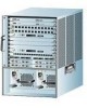
• Route Processors • Switch Modules • Power Supplies • Fan Assembly The chassis ships populated specifically to your order. Figure 1-1 shows an example of a fully populated Catalyst 8540 chassis. Note Refer to the Catalyst 8540 CSR Route Processor and Interface Module Installation Guide for detailed - Cisco 8540 | User Guide - Page 20
Overview 32600 INPUT FAN OUTPUT OK OK FAIL INPUT FAN OK OK Power supply 0 Power supply 1 Interface Modules and Port Adapters The Catalyst 8540 interface modules and port adapters provide ports for connection to network services. You can install up to eight hot-swappable, full-width interface - Cisco 8540 | User Guide - Page 21
modules from the system. To force the standby switch module to become active, use the redundancy preferred-switch-card-slots command. Figure 1-3 shows the switch module. Figure 1-3 Switch Module STATUS ASCTATNIVDEBY SWITCH PROCESSOR 32602 78-6134-03 Catalyst 8540 Chassis Installation Guide - Cisco 8540 | User Guide - Page 22
the rear. (See Figure 1-4.) Note If the power supply shuts down, turn the power switch off (0), wait several minutes for the supply to cool, and then turn the power switch on ( | ). If the power supply shuts down again, remove and replace it. Catalyst 8540 Chassis Installation Guide 1-4 78-6134-03 - Cisco 8540 | User Guide - Page 23
by identifying and resolving adverse conditions before the system fails. Environmental monitoring functions constantly monitor the internal air temperature of the chassis. 78-6134-03 Catalyst 8540 Chassis Installation Guide 1-5 - Cisco 8540 | User Guide - Page 24
Fan Assembly Chapter 1 Product Overview Catalyst 8540 Chassis Installation Guide 1-6 78-6134-03 - Cisco 8540 | User Guide - Page 25
• Installing Power Supplies • Connecting Power to the Chassis Warning Before you install, operate, or service the system, read the Site Preparation and Safety Guide. This guide contains chassis panels inaccessible and difficult to maintain. 78-6134-03 Catalyst 8540 Chassis Installation Guide 2-1 - Cisco 8540 | User Guide - Page 26
interface modules, and switch modules ship installed in the chassis. Refer to the Catalyst 8540 CSR Route Processor and Interface Module Installation Guide for detailed information about the Catalyst 8540 CSR cables and port pinouts. Refer to the Processor Installation Guide and the ATM Port Adapter - Cisco 8540 | User Guide - Page 27
-24 screws • 16 10-32 screws • A disposable ESD strap To install the chassis in a rack, follow these steps: Step 1 Prepare for installation as follows: a. Use a tape measure to measure the depth of the that the rack is otherwise stabilized. 78-6134-03 Catalyst 8540 Chassis Installation Guide 2-3 - Cisco 8540 | User Guide - Page 28
the cable guides on the sides of the chassis between the L brackets and the chassis. Secure the cable guides and the L brackets to the chassis using the ten M3 Phillips countersunk-head screws provided in the rack-mount kit. (See Figure 2-2.) Catalyst 8540 Chassis Installation Guide 2-4 78-6134 - Cisco 8540 | User Guide - Page 29
Chassis Rack-Mounting the Chassis Figure 2-2 Attaching L Brackets and Cable Guides Cable guide 33012 L bracket Step 5 Install the chassis in the rack as follows: a. Grasp the bottom edge front of the chassis between the mounting posts. 78-6134-03 Catalyst 8540 Chassis Installation Guide 2-5 - Cisco 8540 | User Guide - Page 30
mounting post. f. Use a tape measure and level to ensure that the chassis is straight and level. Check the release levers to ensure that all modules are installed securely and tighten any loose captive installation screws on all modules. Catalyst 8540 Chassis Installation Guide 2-6 78-6134-03 - Cisco 8540 | User Guide - Page 31
power supply, follow these steps: Step 1 Grasp the power supply handle with one hand. Place your other hand underneath to support the bottom of the supply. (See Figure 2-4.) Figure 2-4 Handling a Power Supply 32607 INPUT OK FAN OUTPUT OK FAIL 78-6134-03 Catalyst 8540 Chassis Installation Guide - Cisco 8540 | User Guide - Page 32
DC Power Supply Note Install proper grounding to avoid damage from lightning and power surges. Connecting the AC Power Supply To connect power to an AC power supply, follow these steps: Step 1 Plug a power cord into the power cord connection of one AC power supply. (See Figure 2-5.) Catalyst 8540 - Cisco 8540 | User Guide - Page 33
other end of the AC power supply cord to an input line. Plug the power cord into the power cord connection of the redundant power supply. Connect the redundant AC power supply cord to an input line other than the initial power supply line. 78-6134-03 Catalyst 8540 Chassis Installation Guide 2-9 - Cisco 8540 | User Guide - Page 34
the two screws at the top and bottom of the terminal block cover. (See Figure 2-6.) Figure 2-6 DC Power Supply (Terminal Block Cover Shown) 17116 Terminal block cover Power switch o INPUT OK FAN OUTPUT OK FAIL LEDs Captive screw 2-10 Catalyst 8540 Chassis Installation Guide 78-6134-03 - Cisco 8540 | User Guide - Page 35
the above connections. Note Route the wires from the top of the terminal block so that you do not obstruct access to the chassis power switch. Step 6 Reinstall the terminal block cover after ensuring that all wire connections are secure. 78-6134-03 Catalyst 8540 Chassis Installation Guide 2-11 - Cisco 8540 | User Guide - Page 36
state of the power supply • Fan OK LED indicates the operating state of the power supply fan • Output Fail LED indicates the output voltage is outside of proper range Figure 2-8 Power Supply LEDs 32599 INPUT OK FAN OUTPUT OK FAIL LEDs 2-12 Catalyst 8540 Chassis Installation Guide 78-6134-03 - Cisco 8540 | User Guide - Page 37
Green Off Red Off Description Power supply is on and receiving source power. Failure. Fan assembly is operating properly. Failure. Output voltage is outside of proper range, +3.3, +5, +12, and +42 VDC. Output voltage is in proper range. 78-6134-03 Catalyst 8540 Chassis Installation Guide 2-13 - Cisco 8540 | User Guide - Page 38
Connecting Power to the Chassis Chapter 2 Installing the Chassis 2-14 Catalyst 8540 Chassis Installation Guide 78-6134-03 - Cisco 8540 | User Guide - Page 39
the system. Note Refer to the Catalyst 8540 CSR Route Processor and Interface Module Installation Guide for detailed information about the maintenance of the Catalyst 8540 CSR route processors and interface modules. Refer to the Processor Installation Guide and the ATM Port Adapter and Interface - Cisco 8540 | User Guide - Page 40
the chassis. The grounded chassis M4 pemnuts require M4 bolts and locking hardware, which are not included. Tools Required To replace a power supply, you need the following tools: • A 1/4-inch flat-blade screwdriver • A power supply bay cover Catalyst 8540 Chassis Installation Guide 3-2 78-6134-03 - Cisco 8540 | User Guide - Page 41
the power supply handle with one hand. Slowly pull the power supply out of the chassis toward you. While holding the power supply handle with one hand, place your other hand underneath to support the bottom of the supply. (See Figure 3-2.) 78-6134-03 Catalyst 8540 Chassis Installation Guide 3-3 - Cisco 8540 | User Guide - Page 42
aside. Install a power supply cover plate over the power supply bay opening and secure it with the mounting screws if the power supply bay is to remain empty. To install the AC power supply, see the "Installing Power Supplies" section on page 2-7. Catalyst 8540 Chassis Installation Guide 3-4 78 - Cisco 8540 | User Guide - Page 43
the power supply handle with one hand. Slowly pull the power supply out of the chassis toward you. While holding the power supply handle with one hand, place your other hand underneath to support the bottom of the supply. (See Figure 3-2.) 78-6134-03 Catalyst 8540 Chassis Installation Guide 3-5 - Cisco 8540 | User Guide - Page 44
To install the DC power supply, see the "Installing Power Supplies" section on page 2-7. Replacing the Fan Assembly This section describes how to replace the fan assembly, which is a single unit that draws in cooling air and distributes it across the route processor, switch modules, and interface - Cisco 8540 | User Guide - Page 45
overtemperature condition can result in severe equipment damage. Tools Required You need a 3/16-inch flat-blade screwdriver to remove the fan assembly. 78-6134-03 Catalyst 8540 Chassis Installation Guide 3-7 - Cisco 8540 | User Guide - Page 46
if the power has not been turned off. Caution Never operate the system if the fan assembly is not functioning properly or if a fan assembly is not quickly reinstalled. An overtemperature condition can result in severe equipment damage. Catalyst 8540 Chassis Installation Guide 3-8 78-6134 - Cisco 8540 | User Guide - Page 47
captive installation screws. Verify fan assembly operation by checking the fan assembly LED. (See Figure 3-5.) The Fan LED turns green when operating properly. Figure 3-5 Fan LED Fan LED INPUT OK FAN OUTPUT OK FAIL INPUT FAN OK OK 34040 78-6134-03 Catalyst 8540 Chassis Installation Guide - Cisco 8540 | User Guide - Page 48
Replacing the Fan Assembly Chapter 3 Maintaining the Chassis 3-10 Catalyst 8540 Chassis Installation Guide 78-6134-03 - Cisco 8540 | User Guide - Page 49
cable guide: 21.64 in. (55.0 cm) Power supply: 7.1 x 7.9 x 15.3 in. (20.1 x 18.1 x 38.9 cm) Weight Airflow Chassis only: 70 lb (31.7 kg) Chassis fully configured with 2 route processors, 8 line modules, 3 switch modules, and 2 power supplies:160 lb (72.5 kg) AC power supply: 22 lb DC power supply - Cisco 8540 | User Guide - Page 50
with maximum configuration AC current Heat dissipation Rated 16 to 8A Maximum power budget: 17.6A @ 100 VAC, 60 Hz 14.6A @ 115 VAC, 60 Hz; 7A @ 230 VAC, 50 Hz with chassis fully configured 1760W (6000 Btu/hr15) AC frequency 50 to 60 Hz Catalyst 8540 Chassis Installation Guide A-2 78-6134 - Cisco 8540 | User Guide - Page 51
LightStream 1010 port adapters installed in a Catalyst 8540 MSR chassis may not be EMI compliant. An EMI strip ships with the chassis for installation on the port adapters to meet EMI compliance. 10. FCC = Federal Communications Commission. 78-6134-03 Catalyst 8540 Chassis Installation Guide A-3 - Cisco 8540 | User Guide - Page 52
Appendix A Chassis and Power Supply Specifications 11. ICES = Interference-Causing Equipment Standard. 12. VCCI = Voluntary Control Council for Information Technology Equipment. 13. minimum input voltage for the installation is not violated. Catalyst 8540 Chassis Installation Guide A-4 78-6134-03 - Cisco 8540 | User Guide - Page 53
in this guide in multiple languages. Note Additional translated safety warnings can be found in the Regulatory Compliance and Safety Information for the Catalyst 8500 and LightStream 1010 Series document. Safety Information Referral Warning Warning Before you install, operate, or service the - Cisco 8540 | User Guide - Page 54
ao sistema, leia o Guia de Preparação e Segurança do Local. Este guia contém informações de segurança importantes que deve conhecer antes de trabalhar com o sistema. Catalyst 8540 Chassis Installation Guide B-2 78-6134-03 - Cisco 8540 | User Guide - Page 55
de panier d'alimentation reçoit de très hautes tensions. Warnung Hände und Finger nicht in Stromversorgungs-Bays stecken! Wenn das System in Betrieb, steht die Power-Backplane unter Hochspannung. 78-6134-03 Catalyst 8540 Chassis Installation Guide B-3 - Cisco 8540 | User Guide - Page 56
asennettaessa on maahan yhdistäminen aina tehtävä ensiksi ja maadoituksen irti kytkeminen viimeiseksi. Attention Lors de l'installation de l'appareil, la mise à la terre doit toujours être connectée en premier et déconnectée en dernier. Catalyst 8540 Chassis Installation Guide B-4 78-6134-03 - Cisco 8540 | User Guide - Page 57
a ser ligada, e a última a ser desligada. ¡Advertencia! Al instalar el equipo, conectar la tierra la primera y desconectarla la última. Varning! Vid installation av enheten måste jordledningen alltid anslutas först och kopplas bort sist. 78-6134-03 Catalyst 8540 Chassis Installation Guide B-5 - Cisco 8540 | User Guide - Page 58
Ground Connection Warning Appendix B Translated Safety Warnings Catalyst 8540 Chassis Installation Guide B-6 78-6134-03 - Cisco 8540 | User Guide - Page 59
1-1 specifications A-1 Cisco Connection Online. See CCO components descriptions 1-1 fan assembly 3-6 related documentation xi replacing 3-1 D DC power connecting 2-10 connecting redundant 2-10 installing 2-7 maximum dissipated power A-3 powering up 2-10 Catalyst 8540 Chassis Installation Guide 1 - Cisco 8540 | User Guide - Page 60
-ROM xiii conventions viii CSR xi feedback xvi MSR xiii obtaining xiii ordering xiv organization viii related xi software configuration xi www xiii E electromagnetic interference. See EMI EMI compliance A-2, A-3 specifications A-2 Catalyst 8540 Chassis Installation Guide 2 environmental monitoring - Cisco 8540 | User Guide - Page 61
1-4 removing 2-7 shutdown (note) 1-4 temperature 1-4 voltage monitoring 1-5 See also AC power See also DC power R rack-mounting equipment 2-2 procedures 2-2 tools 2-2 redundancy description 1-3 power supplies 1-4 route processor 1-3 switch modules 1-3 Catalyst 8540 Chassis Installation Guide 3 - Cisco 8540 | User Guide - Page 62
warnings B-1 site environment layout 2-1 preparing 2-1 specifications AC power supply A-2 airflow A-1 chassis A-1 DC power supply A-3 switch modules description 1-3 redundancy 1-3 related documentation 1-1 Catalyst 8540 Chassis Installation Guide 4 slots 1-3 T TAC contacts xv description xiv, xv - Cisco 8540 | User Guide - Page 63
Index description ix translations B-1 78-6134-03 Catalyst 8540 Chassis Installation Guide 5 - Cisco 8540 | User Guide - Page 64
Index Catalyst 8540 Chassis Installation Guide 6 78-6134-03
-
 1
1 -
 2
2 -
 3
3 -
 4
4 -
 5
5 -
 6
6 -
 7
7 -
8
-
9
-
10
-
11
-
12
-
13
-
14
-
15
-
16
-
17
-
18
-
19
-
20
-
21
-
22
-
23
-
24
-
25
-
26
-
27
-
28
-
29
-
30
-
31
-
32
-
33
-
34
-
35
-
36
-
37
-
38
-
39
-
40
-
41
-
42
-
43
-
44
-
45
-
46
-
47
-
48
-
49
-
50
-
51
-
52
-
53
-
54
-
55
-
56
-
57
-
58
-
59
-
60
-
61
-
62
-
63
-
64
 |
 |

Cisco Reader Comment Card
General Information
1
Years of networking experience
Years of experience with Cisco products
2
I have these network types:
LAN
Backbone
WAN
Other:
3
I have these Cisco products:
Switches
Routers
Other: Specify model(s)
4
I perform these types of tasks:
H/W Install and/or Maintenance
S/W Config
Network Management
Other:
5
I use these types of documentation:
H/W Install
H/W Config
S/W Config
Command Reference
Quick Reference
Release Notes
Online Help
Other:
6
I access this information through:
Cisco Connection Online (CCO)
CD-ROM
Printed docs
Other:
7
Which method do you prefer?
8
I use the following three product features the most:
Document Information
Document Title: Catalyst 8540 Chassis Installation Guide
Part Number: 78-6134-03
On a scale of 1–5 (5 being the best) please let us know how we rate in the following areas:
Please comment on our lowest score(s):
Mailing Information
Company Name
Date
Contact Name
Job Title
Mailing Address
City
State/Province
ZIP/Postal Code
Country
Phone (
)
Extension
Fax (
)
E-mail
Can we contact you further concerning our documentation?
Yes
No
You can also send us your comments by e-mail to
, or fax your comments to us at
(408) 527-8089
.
The document was written at my
technical level of understanding.
The information was accurate.
The document was complete.
The information I wanted was easy to find.
The information was well organized.
The information I found was useful to my job.
%
%
%
%