Cisco AIR-AP1210 Hardware Installation Guide
Cisco AIR-AP1210 - Aironet 1200 - Wireless Access Point External Manual
 |
UPC - 746320804330
View all Cisco AIR-AP1210 manuals
Add to My Manuals
Save this manual to your list of manuals |
Cisco AIR-AP1210 manual content summary:
- Cisco AIR-AP1210 | Hardware Installation Guide - Page 1
Cisco Aironet 1200 Series Access Point Hardware Installation Guide Corporate Headquarters Cisco Systems, Inc. 170 West Tasman Drive San Jose, CA 95134-1706 USA http://www.cisco.com Tel: 408 526-4000 800 553-NETS (6387) Fax: 408 526-4100 Customer Order Number: Text Part Number: OL-4310-01 - Cisco AIR-AP1210 | Hardware Installation Guide - Page 2
with the instruction manual, may Cisco Arrow logo, the Cisco Powered Network mark, Cisco Unity, Follow Me Browsing, FormShare, and StackWise are trademarks of Cisco Systems, Inc.; Changing the Way We Work, Live, Play, and Learn, and iQuick Study are service marks of Cisco Systems, Inc.; and Aironet - Cisco AIR-AP1210 | Hardware Installation Guide - Page 3
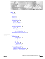
Port 1-2 LEDs 1-3 Power Sources 1-3 UL 2043 Certification 1-4 Anti-Theft Features 1-4 Network Configuration Examples 1-5 Root Unit on a Wired LAN 1-5 Repeater Unit that Extends Wireless Range 1-6 Central Unit in an All-Wireless Network 1-7 CONTENTS OL-4310-01 Cisco Aironet 1200 Series Access - Cisco AIR-AP1210 | Hardware Installation Guide - Page 4
Set the Access Point's IP Address and SSID 3-11 Assigning an IP Address Using the CLI 3-12 Using a Telnet Session to Access the CLI 3-12 Cisco Aironet 1200 Series Access Point Hardware Installation Guide iv OL-4310-01 - Cisco AIR-AP1210 | Hardware Installation Guide - Page 5
Shell 5-9 Mounting Instructions 6-1 Overview 6-2 Mounting on a Horizontal or Vertical Surface 6-3 Mounting on a Suspended Ceiling 6-4 Attaching the Access Point to the Mounting Bracket 6-5 Securing the Access Point to the Mounting Bracket 6-5 Contents OL-4310-01 Cisco Aironet 1200 Series Access - Cisco AIR-AP1210 | Hardware Installation Guide - Page 6
Radio Module 8-5 Troubleshooting 9-1 Checking the Top Panel LEDs 9-2 Checking Basic Settings 9-4 SSID 9-4 WEP Keys 9-4 Security Settings 9-5 Resetting to the Image File 9-8 Obtaining the TFTP Server Software 9-9 Cisco Aironet 1200 Series Access Point Hardware Installation Guide vi OL-4310-01 - Cisco AIR-AP1210 | Hardware Installation Guide - Page 7
of Conformity for RF Exposure B-6 Guidelines for Operating Cisco Aironet Access Points in Power Levels D-4 IEEE 802.11a D-4 IEEE 802.11b D-4 Console Cable Pinouts E-1 Overview E-2 Console Port Signals and Pinouts E-2 OL-4310-01 Cisco Aironet 1200 Series Access Point Hardware Installation Guide - Cisco AIR-AP1210 | Hardware Installation Guide - Page 8
Contents Cisco Aironet 1200 Series Access Point Hardware Installation Guide viii OL-4310-01 - Cisco AIR-AP1210 | Hardware Installation Guide - Page 9
, refer to the IOS documentation set available from the Cisco.com home page at Service and Support > Technical Documents. On the Cisco Product Documentation home page, select Release 12.2 from the Cisco IOS Software drop-down menu. This guide also includes an overview of the access point web-based - Cisco AIR-AP1210 | Hardware Installation Guide - Page 10
, cautions, and timesavers use these conventions and symbols: Tip Means the following will help you solve a problem. The tips information might not be troubleshooting or even an action, but could be useful information. Cisco Aironet 1200 Series Access Point Hardware Installation Guide x OL-4310-01 - Cisco AIR-AP1210 | Hardware Installation Guide - Page 11
note. Notes contain helpful suggestions or references to materials not contained in this manual. Caution Means reader be careful. In this situation, you might do something (Traduzione delle avvertenze di sicurezza). OL-4310-01 Cisco Aironet 1200 Series Access Point Hardware Installation Guide xi - Cisco AIR-AP1210 | Hardware Installation Guide - Page 12
Notes for 1200 Series Access Points • Cisco Aironet 1200 Series Access Point Command Reference • Cisco IOS Software Configuration Guide for Cisco Aironet Access Points Click this link to browse to the Cisco Aironet documentation home page: http://www.cisco.com/univercd/cc/td/doc/product/wireless - Cisco AIR-AP1210 | Hardware Installation Guide - Page 13
(if present) behind the front cover of your document or by writing to the following address: Cisco Systems Attn: Customer Document Ordering 170 West Tasman Drive San Jose, CA 95134-9883 We appreciate your comments. OL-4310-01 Cisco Aironet 1200 Series Access Point Hardware Installation Guide xiii - Cisco AIR-AP1210 | Hardware Installation Guide - Page 14
, troubleshooting tips, and sample configurations from the Cisco TAC website. Cisco.com registered users have complete access to the technical support resources on the Cisco TAC website, including TAC tools and utilities. Cisco.com Cisco.com offers a suite of interactive, networked services that - Cisco AIR-AP1210 | Hardware Installation Guide - Page 15
, Internetworking Technology Handbook, Internetworking Troubleshooting Guide, and the Internetworking Design Guide. For current Cisco Press titles and other information, go to Cisco Press online at this URL: http://www.ciscopress.com OL-4310-01 Cisco Aironet 1200 Series Access Point Hardware - Cisco AIR-AP1210 | Hardware Installation Guide - Page 16
.html • Training-Cisco offers world-class networking training. Current offerings in network training are listed at this URL: http://www.cisco.com/en/US/learning/le31/learning_recommended_training_list.html Cisco Aironet 1200 Series Access Point Hardware Installation Guide xvi OL-4310 - Cisco AIR-AP1210 | Hardware Installation Guide - Page 17
module in an external, modified cardbus slot. The access point supports one radio of each type, but it does not support two 2.4-GHz or two 5-GHz radios. You can configure the • Network Configuration Examples, page 1-5 OL-4310-01 Cisco Aironet 1200 Series Access Point Hardware Installation Guide 1-1 - Cisco AIR-AP1210 | Hardware Installation Guide - Page 18
Pinouts," for a description of the console port pinouts.) Assign the following port settings to a terminal emulator to open the management system pages: 9600 baud, 8 data bits, No parity, 1 stop bit and no flow control. Cisco Aironet 1200 Series Access Point Hardware Installation Guide 1-2 OL-4310 - Cisco AIR-AP1210 | Hardware Installation Guide - Page 19
power using the Ethernet cable. Using inline power, you do not need to run a separate power cord to the access point. The access point supports the following power sources: • Power supply (input 100-240 VAC, 50-60 Hz, output 48 VDC, 0.2A minimum) • Inline power from: - Cisco Aironet Power Injector - Cisco AIR-AP1210 | Hardware Installation Guide - Page 20
the security hasp, you can lock the access point to the bracket with a padlock. Compatible padlocks are Master Lock models 120T and 121T or equivalent. Cisco Aironet 1200 Series Access Point Hardware Installation Guide 1-4 OL-4310-01 - Cisco AIR-AP1210 | Hardware Installation Guide - Page 21
a wired LAN. Figure 1-2 Access Points as Root Units on a Wired LAN Access Point (Root Unit) Wired LAN Access Point (Root Unit) 65999 OL-4310-01 Cisco Aironet 1200 Series Access Point Hardware Installation Guide 1-5 - Cisco AIR-AP1210 | Hardware Installation Guide - Page 22
. Figure 1-3 shows an access point acting as a repeater. Consult the Cisco IOS Software Configuration Guide for Cisco Aironet Access Points for instructions on setting up an access point as a repeater. Note Non-Cisco client devices might have difficulty communicating with repeater access points - Cisco AIR-AP1210 | Hardware Installation Guide - Page 23
access point in an all-wireless network. Figure 1-4 Access Point as Central Unit in All-Wireless Network Access Point (Root Unit) 65998 OL-4310-01 Cisco Aironet 1200 Series Access Point Hardware Installation Guide 1-7 - Cisco AIR-AP1210 | Hardware Installation Guide - Page 24
Network Configuration Examples Chapter 1 Overview Cisco Aironet 1200 Series Access Point Hardware Installation Guide 1-8 OL-4310-01 - Cisco AIR-AP1210 | Hardware Installation Guide - Page 25
Basic Installation Guidelines, page 2-3 • Before Beginning the Installation, page 2-4 • Installation Summary, page 2-5 • Connecting the 2.4-GHz Antennas, page 2-5 • Connecting the Ethernet and Power Cables, page 2-6 OL-4310-01 Cisco Aironet 1200 Series Access Point Hardware Installation Guide 2-1 - Cisco AIR-AP1210 | Hardware Installation Guide - Page 26
(RF) electromagnetic energy emitted by FCC certified equipment. When used with approved Cisco Aironet antennas, Cisco Aironet products meet the uncontrolled environmental limits found in OET-65 and ANSI C95.1, 1991. Proper installation of this radio according to the instructions found in this manual - Cisco AIR-AP1210 | Hardware Installation Guide - Page 27
accordance with Section 300-22(c) of the NEC. For mounting instructions, refer to the Chapter 6, "Mounting Instructions." Caution Cisco Aironet power injectors are not tested to UL 2043 and should not be placed in a building's environmental air space, such as above suspended ceilings. Note If you - Cisco AIR-AP1210 | Hardware Installation Guide - Page 28
2 48-VDC power port 3 Ethernet port (RJ-45) 4 Console port (RJ-45) Figure 2-2 5-GHz Radio Module 1 1 2 5 Mode button 6 Status LEDs 7 Mounting bracket 3 74631 1 5-GHz radio module mounting screws 3 Access point 2 5-GHz radio module antenna (patch position) Cisco Aironet 1200 Series Access - Cisco AIR-AP1210 | Hardware Installation Guide - Page 29
, refer toChapter 6, "Mounting Instructions." Connecting the 2.4-GHz Antennas The access point supports a single antenna or dual diversity antennas. Two R-TNC antenna connectors are provided on the back of the unit for the 2.4-GHz radio. If you are using a Cisco Aironet 2 dBi antenna, follow the - Cisco AIR-AP1210 | Hardware Installation Guide - Page 30
, 3550-24 PWR, 4000, or 6500 switch • An inline power patch panel, such as a Cisco Catalyst Inline Power Patch Panel • A power injector • A power module (Universal power supply) Note Currently, the Catalyst 3550-24 PWR switch supports power for both the 2.4-GHz radio and the 5-GHz radio. Other - Cisco AIR-AP1210 | Hardware Installation Guide - Page 31
the other end labeled To Network to the 10/100 Ethernet LAN. Note If you use a power supply or power injector to power the access point, you must use the power supply included with your access point and the Cisco Aironet Power Injector for the 1100 and 1200 series access points. Connecting to - Cisco AIR-AP1210 | Hardware Installation Guide - Page 32
LED descriptions. When the sequence is complete, you are ready to obtain the access point's IP address and perform an initial configuration. Refer to Chapter 3, "Configuring the Access Point for the First Time," for instructions on assigning basic settings to the access point. Cisco Aironet 1200 - Cisco AIR-AP1210 | Hardware Installation Guide - Page 33
the first time. The contents of this chapter are similar to the instructions in the quick start guide that shipped with your access point. You can configure all the settings described to Access the CLI, page 3-12 OL-4310-01 Cisco Aironet 1200 Series Access Point Hardware Installation Guide 3-1 - Cisco AIR-AP1210 | Hardware Installation Guide - Page 34
Software screen appears. Click System Configuration and the System Configuration screen appears. Click the Reset to Defaults button. Note If the access point is configured with a static IP address, the IP address does not change. Cisco Aironet 1200 Series Access Point Hardware Installation Guide - Cisco AIR-AP1210 | Hardware Installation Guide - Page 35
's MAC address is on label attached to the bottom of the access point. - Use the Cisco IP Setup Utility (IPSU) to identify the assigned address. You can also use IPSU to assign 45 serial cable RJ-45 serial connector OL-4310-01 Cisco Aironet 1200 Series Access Point Hardware Installation Guide 3-3 - Cisco AIR-AP1210 | Hardware Installation Guide - Page 36
Time Note The Cisco part number for the DB-9 to RJ-45 serial cable is AIR-CONCAB1200. Browse to http://www.cisco.com/go/marketplace Cisco and press Enter. The Summary Status page appears. Figure 3-2 shows the Summary Status page. Cisco Aironet 1200 Series Access Point Hardware Installation Guide - Cisco AIR-AP1210 | Hardware Installation Guide - Page 37
Figure 3-2 Summary Status Page Assigning Basic Settings Step 5 Click Express Setup. The Express Setup screen appears. Figure 3-3 shows the Express Setup page. OL-4310-01 Cisco Aironet 1200 Series Access Point Hardware Installation Guide 3-5 - Cisco AIR-AP1210 | Hardware Installation Guide - Page 38
are automatically assigned by your network's DHCP server. - Static IP-The access point uses a static IP address that you enter in the IP address field. Cisco Aironet 1200 Series Access Point Hardware Installation Guide 3-6 OL-4310-01 - Cisco AIR-AP1210 | Hardware Installation Guide - Page 39
new IP address. Follow the steps in the "Resetting the Access Point to Default Settings" section on field blank. • Radio Service Set ID (SSID)-Enter the manual for the information you need to complete the configuration. OL-4310-01 Cisco Aironet 1200 Series Access Point Hardware Installation Guide - Cisco AIR-AP1210 | Hardware Installation Guide - Page 40
by unplugging the power jack and plugging Radio Service Set Cisco IOS Software Configuration Guide for Cisco Aironet Access Points) • WEP and additional WEP features, such as TKIP and broadcast key rotation (see Cisco IOS Software Configuration Guide for Cisco Aironet Access Points) Cisco Aironet - Cisco AIR-AP1210 | Hardware Installation Guide - Page 41
Cisco IOS Software Configuration Guide for Cisco Aironet Access Aironet Wireless Software Display Tables. Locate the access point firmware and utilities section and click Cisco Aironet 1200 Series (Cisco IOS Software). Click IPSUvxxxxxx.exe. The vxxxxxx identifies the software package version number - Cisco AIR-AP1210 | Hardware Installation Guide - Page 42
from the default value using IPSU, refer to the "Using IPSU to Set the Access Point's IP Address and SSID" section on page 3-11. 3-10 Cisco Aironet 1200 Series Access Point Hardware Installation Guide OL-4310-01 - Cisco AIR-AP1210 | Hardware Installation Guide - Page 43
You cannot set the SSID without also setting the IP address. However, you can set the IP address without setting the SSID. OL-4310-01 Cisco Aironet 1200 Series Access Point Hardware Installation Guide 3-11 - Cisco AIR-AP1210 | Hardware Installation Guide - Page 44
of tracking separate IP addresses for the access point's Ethernet and radio ports, the network uses the BVI. application. Check your PC operating instructions for detailed instructions for your operating system. Step Cisco Aironet 1200 Series Access Point Hardware Installation Guide OL-4310-01 - Cisco AIR-AP1210 | Hardware Installation Guide - Page 45
settings, upgrade firmware, and monitor and configure other wireless devices on the network. Note The access point web-browser interface is fully compatible with Microsoft Internet Explorer (version 5.x or later) or Netscape Navigator (version 4.x). OL-4310-01 Cisco Aironet 1200 Series Access - Cisco AIR-AP1210 | Hardware Installation Guide - Page 46
system. See the "Obtaining and Assigning an IP Address" section on page 3-3 for instructions on assigning an IP address to the access point. Follow these steps to begin using web-browser interface home page. Cisco Aironet 1200 Series Access Point Hardware Installation Guide 4-2 OL-4310-01 - Cisco AIR-AP1210 | Hardware Installation Guide - Page 47
Chapter 4 Using the Web-Browser Interface Using the Management Pages in the Web-Browser Interface Figure 4-1 Web-Browser Interface Home Page OL-4310-01 Cisco Aironet 1200 Series Access Point Hardware Installation Guide 4-3 - Cisco AIR-AP1210 | Hardware Installation Guide - Page 48
to security configuration pages. Services Displays status for several access point features and links to configuration pages for Telnet/SSH, CDP, domain name server, filters, proxy Mobile IP, QoS, SNMP, SNTP, and VLANs. System Software Displays the version number of the firmware that the access - Cisco AIR-AP1210 | Hardware Installation Guide - Page 49
Entry Fields Because the 1200 series access point uses Cisco IOS software, there are certain characters that you cannot use in help index or instructions for common configuration tasks, such as configuring VLANs. OL-4310-01 Cisco Aironet 1200 Series Access Point Hardware Installation Guide 4-5 - Cisco AIR-AP1210 | Hardware Installation Guide - Page 50
Using Online Help Chapter 4 Using the Web-Browser Interface Cisco Aironet 1200 Series Access Point Hardware Installation Guide 4-6 OL-4310-01 - Cisco AIR-AP1210 | Hardware Installation Guide - Page 51
5-4 • Using Command History, page 5-4 • Using Editing Features, page 5-5 • Searching and Filtering Output of show and more Commands, page 5-8 • Accessing the CLI, page 5-8 OL-4310-01 Cisco Aironet 1200 Series Access Point Hardware Installation Guide 5-1 - Cisco AIR-AP1210 | Hardware Installation Guide - Page 52
Interface IOS Command Modes The Cisco IOS user interface is Ethernet exit. To return to and radio interfaces. The privileged EXEC mode, 2.4-GHz radio is radio 0, and press Ctrl-Z or enter end. the 5-GHz radio is radio 1. Cisco Aironet 1200 Series Access Point Hardware Installation Guide - Cisco AIR-AP1210 | Hardware Installation Guide - Page 53
? abbreviated-command-entry ? command ? command keyword ? Purpose Obtains a brief description of the help system in any command mode. Obtains a list of commands that begin a feature that is disabled by default. OL-4310-01 Cisco Aironet 1200 Series Access Point Hardware Installation Guide 5-3 - Cisco AIR-AP1210 | Hardware Installation Guide - Page 54
buffer. Beginning in privileged EXEC mode, enter this command to change the number of command lines that the access point records during the current terminal session: ap# terminal history [size number-of-lines] Cisco Aironet 1200 Series Access Point Hardware Installation Guide 5-4 OL-4310-01 - Cisco AIR-AP1210 | Hardware Installation Guide - Page 55
EXEC mode, list the last several commands that you just entered. The number of commands that are displayed is determined by the setting of the terminal Keystrokes, page 5-6 • Editing Command Lines that Wrap, page 5-7 OL-4310-01 Cisco Aironet 1200 Series Access Point Hardware Installation Guide 5-5 - Cisco AIR-AP1210 | Hardware Installation Guide - Page 56
the beginning of the command line. Delete the word to the left of the cursor. Delete from the cursor to the end of the word. Cisco Aironet 1200 Series Access Point Hardware Installation Guide 5-6 OL-4310-01 - Cisco AIR-AP1210 | Hardware Installation Guide - Page 57
.255.0 131.108.1.20 255.255.255.0 eq ap(config)# $108.2.5 255.255.255.0 131.108.1.20 255.255.255.0 eq 45 OL-4310-01 Cisco Aironet 1200 Series Access Point Hardware Installation Guide 5-7 - Cisco AIR-AP1210 | Hardware Installation Guide - Page 58
131.108.2.5 255.255.255.0 131.108.1$ The software assumes you have a terminal screen that is 80 columns application. Check your PC operating instructions for detailed instructions for your operating system. Step Cisco Aironet 1200 Series Access Point Hardware Installation Guide 5-8 OL-4310-01 - Cisco AIR-AP1210 | Hardware Installation Guide - Page 59
.ssh.com/ SSH provides more security for remote connections than Telnet by providing strong encryption when a device is authenticated. See the Cisco IOS Software Configuration Guide for Cisco Aironet Access Points for detailed instructions on setting up the access point for SSH access. OL-4310-01 - Cisco AIR-AP1210 | Hardware Installation Guide - Page 60
Accessing the CLI Chapter 5 Using the Command-Line Interface 5-10 Cisco Aironet 1200 Series Access Point Hardware Installation Guide OL-4310-01 - Cisco AIR-AP1210 | Hardware Installation Guide - Page 61
CH A P T E R 6 This appendix provides instructions for mounting the access point to suspended ceilings, vertical surfaces, or Bracket, page 6-5 • Securing the Access Point to the Mounting Bracket, page 6-5 OL-4310-01 Cisco Aironet 1200 Series Access Point Hardware Installation Guide 6-1 - Cisco AIR-AP1210 | Hardware Installation Guide - Page 62
Cisco Aironet 1200 Series Access Point provides adequate fire resistance and low smoke-producing characteristics suitable for operation in a building's environmental air a building's environmental air space, you must use Ethernet cable suitable for operation in environmental air space in accordance - Cisco AIR-AP1210 | Hardware Installation Guide - Page 63
Chapter 6 Mounting Instructions Mounting on a Horizontal or Vertical Surface A mounting hardware kit is provided that contains the it to a stud or major structural member and using the appropriate fasteners. OL-4310-01 Cisco Aironet 1200 Series Access Point Hardware Installation Guide 6-3 - Cisco AIR-AP1210 | Hardware Installation Guide - Page 64
bracket. You should review Figure 6-2 before beginning the mounting process. Figure 6-2 Mounting Bracket Parts 1 2 2 3 3 4 5 1 Suspended ceiling T-rail 2 Caddy fastener 3 Plastic spacer 5 4 Mounting bracket 5 Keps nut (contains an attached lock washer) 74121 Cisco Aironet 1200 Series Access - Cisco AIR-AP1210 | Hardware Installation Guide - Page 65
Chapter 6 Mounting Instructions Attaching the Access Ethernet cable to the access point's Ethernet port. Insert the 1200 series power module cable connector into the access point's 48-VDC power port (if you are using a local power Cisco Aironet 1200 Series Access Point Hardware Installation Guide 6-5 - Cisco AIR-AP1210 | Hardware Installation Guide - Page 66
Securing the Access Point to the Mounting Bracket Chapter 6 Mounting Instructions Cisco Aironet 1200 Series Access Point Hardware Installation Guide 6-6 OL-4310-01 - Cisco AIR-AP1210 | Hardware Installation Guide - Page 67
upgrade instructions for the 2.4-GHz radio module and includes the following sections: • Upgrade Overview, page 7-2 • Opening the Access Cover, page 7-3 • Removing a Blank Spacer Card, page 7-4 • Removing a 2.4-GHz Radio, page 7-5 • Installing a 2.4-GHz Radio, page 7-7 OL-4310-01 Cisco Aironet - Cisco AIR-AP1210 | Hardware Installation Guide - Page 68
by an ESD-trained service technician at an ESD-protected workstation. Note After you install the new radio, all configurable radio settings will be at default values. Refer to the Cisco IOS Software Configuration Guide for Cisco Aironet Access Points for complete instructions on configuring the new - Cisco AIR-AP1210 | Hardware Installation Guide - Page 69
these steps: Step 1 Step 2 Step 3 Step 4 Step 5 Remove all cables and power connections from the access point. Remove all static-generating items from the work area, such as the "Removing a 2.4-GHz Radio" section. OL-4310-01 Cisco Aironet 1200 Series Access Point Hardware Installation Guide 7-3 - Cisco AIR-AP1210 | Hardware Installation Guide - Page 70
wire) 3 Antenna connector (black wire) Step 2 Carefully bend the card near the slots in opposite directions to provide enough clearance to remove the antenna wires. Cisco Aironet 1200 Series Access Point Hardware Installation Guide 7-4 OL-4310-01 - Cisco AIR-AP1210 | Hardware Installation Guide - Page 71
by their connectors. Step 4 Remove the blank spacer card from the mini-PCI connector. For instructions on installing the radio card, go to the "Installing a 2.4-GHz Radio" section. Removing them by their connectors. OL-4310-01 Cisco Aironet 1200 Series Access Point Hardware Installation Guide 7-5 - Cisco AIR-AP1210 | Hardware Installation Guide - Page 72
. c. Remove the 2.4-GHz card from the mini-PCI connector. Place the removed 2.4GHz radio card into an anti-static bag. For instructions on installing a new radio card, go to the "Installing a 2.4-GHz Radio" section. Cisco Aironet 1200 Series Access Point Hardware Installation Guide 7-6 OL-4310-01 - Cisco AIR-AP1210 | Hardware Installation Guide - Page 73
be damaged by ESD from improper handling. Step 1 Step 2 Step 3 Carefully remove the Cisco Aironet 2.4-GHz radio card from its anti-static bag. Grasp the radio card only on the edges white label (see Figure 7-4). OL-4310-01 Cisco Aironet 1200 Series Access Point Hardware Installation Guide 7-7 - Cisco AIR-AP1210 | Hardware Installation Guide - Page 74
Damage to the radio could occur if the antenna connectors are touching when power is applied. If they are touching, carefully rotate them in opposite directions to the Cisco IOS Software Configuration Guide for Cisco Aironet Access Points. Cisco Aironet 1200 Series Access Point Hardware - Cisco AIR-AP1210 | Hardware Installation Guide - Page 75
provides upgrade instructions for the 5-GHz radio module and includes the following sections: • Upgrade Overview, page 8-2 • Removing the 5-GHz Radio Access Cover, page 8-2 • Removing a 5-GHz Radio Module, page 8-3 • Installing a 5-GHz Radio Module, page 8-5 OL-4310-01 Cisco Aironet 1200 Series - Cisco AIR-AP1210 | Hardware Installation Guide - Page 76
you install the radio module, all configurable radio settings will be at default values. Refer to the Cisco IOS Software Configuration Guide for Cisco Aironet Access Points for complete instructions on configuring the new radio. Unpacking the Radio Module Each 5-GHz radio module is shipped with the - Cisco AIR-AP1210 | Hardware Installation Guide - Page 77
power supplied Torx L-wrench (Figure 8-2). Figure 8-2 5-GHz Radio Module 1 1 2 3 74631 1 Mounting screws 2 5-GHz radio module antenna 3 Access point Note Do not attempt to remove the mounting screws from the module; they are captured in the module housing. OL-4310-01 Cisco Aironet - Cisco AIR-AP1210 | Hardware Installation Guide - Page 78
8-3). Figure 8-3 Removing the 5-GHz Radio Module 74629 Step 5 Fold the antenna down (towards the attached radio card) and insert the module into a static protected bag. Cisco Aironet 1200 Series Access Point Hardware Installation Guide 8-4 OL-4310-01 - Cisco AIR-AP1210 | Hardware Installation Guide - Page 79
3 Access point card-bus slot 4 5-GHz radio card Step 4 Push the 5-GHz radio module into the slot until you hear a slight click. OL-4310-01 Cisco Aironet 1200 Series Access Point Hardware Installation Guide 8-5 - Cisco AIR-AP1210 | Hardware Installation Guide - Page 80
Module Upgrade Step 5 Tighten the 5-GHz radio module mounting screws using the supplied Torx L-wrench (see Figure 8-5). Figure 8-5 Location of Mounting Screws 1 label 2 Access point product compliance label Cisco Aironet 1200 Series Access Point Hardware Installation Guide 8-6 OL-4310-01 - Cisco AIR-AP1210 | Hardware Installation Guide - Page 81
installation is now complete and radio settings are at default values. To configure the 5-GHz radio with your wireless network settings refer to the Cisco IOS Software Configuration Guide for Cisco Aironet Access Points. OL-4310-01 Cisco Aironet 1200 Series Access Point Hardware Installation - Cisco AIR-AP1210 | Hardware Installation Guide - Page 82
Installing a 5-GHz Radio Module Chapter 8 5-GHz Radio Module Upgrade Cisco Aironet 1200 Series Access Point Hardware Installation Guide 8-8 OL-4310-01 - Cisco AIR-AP1210 | Hardware Installation Guide - Page 83
Settings, page 9-4 • Resetting to the Default Configuration, page 9-5 • Reloading the Access Point Image, page 9-6 • Obtaining the Access Point Image File, page 9-8 • Obtaining the TFTP Server Software, page 9-9 OL-4310-01 Cisco Aironet 1200 Series Access Point Hardware Installation Guide 9-1 - Cisco AIR-AP1210 | Hardware Installation Guide - Page 84
to indicate radio traffic activity. The light is normally off, but it blinks green whenever a packet is received or transmitted over the access point's radio. Cisco Aironet 1200 Series Access Point Hardware Installation Guide 9-2 OL-4310-01 - Cisco AIR-AP1210 | Hardware Installation Guide - Page 85
/receive Ethernet errors. - General warning. - Resetting the configuration options to factory defaults. Red Firmware failure; try disconnecting and reconnecting unit power. - Loading new firmware image. OL-4310-01 Cisco Aironet 1200 Series Access Point Hardware Installation Guide 9-3 - Cisco AIR-AP1210 | Hardware Installation Guide - Page 86
exactly the same value. The access point does not need to use Key 3 as its transmit key, however. Refer to the Cisco IOS Software Configuration Guide for Cisco Aironet Access Points for instructions on setting the access point's WEP keys. Cisco Aironet 1200 Series Access Point Hardware Installation - Cisco AIR-AP1210 | Hardware Installation Guide - Page 87
Chapter 9 Troubleshooting Resetting to the Default Configuration Security Settings Wireless clients attempting to authenticate with your access point must support the same security options IP address using DHCP). OL-4310-01 Cisco Aironet 1200 Series Access Point Hardware Installation Guide 9-5 - Cisco AIR-AP1210 | Hardware Installation Guide - Page 88
failure or a corrupt firmware image, indicated by three red LEDs, you must reload the image from a connected TFTP server. Note This process resets all configuration settings to factory defaults, including passwords, WEP keys, the access point IP address, and SSIDs. Cisco Aironet 1200 Series Access - Cisco AIR-AP1210 | Hardware Installation Guide - Page 89
Software Upgrade. The HTTP Upgrade screen appears. Click the Browse button to locate the image file on your PC. Click the Upload button. For additional information, click the Help icon on the Software Upgrade screen. OL-4310-01 Cisco Aironet 1200 Series Access Point Hardware Installation Guide - Cisco AIR-AP1210 | Hardware Installation Guide - Page 90
to access the Cisco Software Center at the following URL: http://www.cisco.com/public/sw-center/sw-wireless.shtml Click Option 2: Aironet Wireless Software Display Tables. Find the access point firmware and utilities section and click Cisco Aironet 1200 Series (Cisco IOS Software). Click c1100-k9w7 - Cisco AIR-AP1210 | Hardware Installation Guide - Page 91
TFTP server software from several web sites. Cisco recommends the shareware TFTP utility available at this URL: http://tftpd32.jounin.net Follow the instructions on the website for installing and using the utility. OL-4310-01 Cisco Aironet 1200 Series Access Point Hardware Installation Guide 9-9 - Cisco AIR-AP1210 | Hardware Installation Guide - Page 92
Obtaining the TFTP Server Software Chapter 9 Troubleshooting 9-10 Cisco Aironet 1200 Series Access Point Hardware Installation Guide OL-4310-01 - Cisco AIR-AP1210 | Hardware Installation Guide - Page 93
: • Dipole Antenna Installation Warning, page A-2 • Explosive Device Proximity Warning, page A-3 • Lightning Activity Warning, page A-4 • Installation Warning, page A-5 • Circuit Breaker (15A) Warning, page A-5 OL-4310-01 Cisco Aironet 1200 Series Access Point Hardware Installation Guide A-1 - Cisco AIR-AP1210 | Hardware Installation Guide - Page 94
a un mínimo de 20 cm (7,9 pulgadas) o más del cuerpo de las personas. Varning! För att följa FCC-exponeringsgränserna för radiofrekvens (RF), bör dipolsantenner placeras på minst 20 cm avstånd från alla människor. Cisco Aironet 1200 Series Access Point Hardware Installation Guide A-2 OL-4310-01 - Cisco AIR-AP1210 | Hardware Installation Guide - Page 95
trådlösa nätverksenheten i närheten av oskyddade tändhattar eller i en explosiv miljö om inte enheten modifierats för att kunna användas i sådana sammanhang. OL-4310-01 Cisco Aironet 1200 Series Access Point Hardware Installation Guide A-3 - Cisco AIR-AP1210 | Hardware Installation Guide - Page 96
transcurso de descargas eléctricas en la atmósfera. Varning! Vid åska skall du aldrig utföra arbete på systemet eller ansluta eller koppla loss kablar. Cisco Aironet 1200 Series Access Point Hardware Installation Guide A-4 OL-4310-01 - Cisco AIR-AP1210 | Hardware Installation Guide - Page 97
Warning Warning Read the installation instructions before you connect the system to its power source. Waarschuwing Raadpleeg de installatie est utilisé sur les conducteurs de phase (conducteurs de charge). OL-4310-01 Cisco Aironet 1200 Series Access Point Hardware Installation Guide A-5 - Cisco AIR-AP1210 | Hardware Installation Guide - Page 98
). Kontrollera att säkring eller överspänningsskydd används på fasledarna (samtliga strömförande ledare) för internationellt bruk max. 240 V växelström, 10 A (i USA max. 120 V växelström, 15 A). Cisco Aironet 1200 Series Access Point Hardware Installation Guide A-6 OL-4310-01 - Cisco AIR-AP1210 | Hardware Installation Guide - Page 99
• Department of Communications-Canada • European Community, Switzerland, Norway, Iceland, and Liechtenstein • Declaration of Conformity for RF Exposure • Guidelines for Operating Cisco Aironet Access Points in Japan OL-4310-01 Cisco Aironet 1200 Series Access Point Hardware Installation Guide B-1 - Cisco AIR-AP1210 | Hardware Installation Guide - Page 100
FOR HOME OR OFFICE USE Models: AIR-AP1200 with AIR-MP20B-A-K9 and/or AIR-RM20A-A-K9, AIR-AP1210, AIR-AP1220B-A-K9, AIR-AP1230B-A-K9, AIR-AP1220A-A-K9, AIR- AP1230A-A-K9, FCC Certification number: LDK 102042 (AIR-MP20B-A-K9) LDK 102045 (AIR-RM20A-A-K9) Manufacturer: Cisco Systems, Inc. 170 West - Cisco AIR-AP1210 | Hardware Installation Guide - Page 101
Cisco Part Number Model Gain AIR-ANT1949 Yagi 13.5 AIR-ANT4121 Omni-directional 12.0 AIR-ANT3549 Patch 8.5 AIR-ANT2012 Spatial diversity 6.5 AIR-ANT1729 Patch 6.0 AIR-ANT2506 Omni-directional 5.1 AIR-ANT3213 Omni-directional 5.0 AIR-ANT1728 Omni-directional 5.0 AIR - Cisco AIR-AP1210 | Hardware Installation Guide - Page 102
oleelliset vaatimukset ja on siinä asetettujen muidenkin ehtojen mukainen. Denna utrustning är i överensstämmelse med de väsentliga kraven och andra relevanta bestämmelser i Direktiv 1999/5/EC. Cisco Aironet 1200 Series Access Point Hardware Installation Guide B-4 OL-4310-01 - Cisco AIR-AP1210 | Hardware Installation Guide - Page 103
1999/5/EC or the CEPT recommendation Rec 70.03 or both. For more details on legal combinations of power levels and antennas, refer to the Cisco IOS Software Configuration Guide for Cisco Aironet Access Points. For 54 Mbps, 5 GHz access points with 40 mW radios, the following standards were applied - Cisco AIR-AP1210 | Hardware Installation Guide - Page 104
, AIR-ANT4121 and AIR-ANT1949 support a minimum separation distance of 10 cm (3.9 in) and are compliant with the applicable FCC RF exposure limit when transmitting simultaneously. Note Dual antennas used for diversity operation are not considered co-located. Guidelines for Operating Cisco Aironet - Cisco AIR-AP1210 | Hardware Installation Guide - Page 105
on avoiding radio interference, such as setting partitions. 3. If this equipment causes RF interference to a specified low-power radio station of RF-ID, contact the number below. Contact Number: 03-5549-6500 OL-4310-01 Cisco Aironet 1200 Series Access Point Hardware Installation Guide B-7 - Cisco AIR-AP1210 | Hardware Installation Guide - Page 106
Guidelines for Operating Cisco Aironet Access Points in Japan Appendix B Declarations of Conformity and Regulatory Information Cisco Aironet 1200 Series Access Point Hardware Installation Guide B-8 OL-4310-01 - Cisco AIR-AP1210 | Hardware Installation Guide - Page 107
injector: 32 to 104oF (0 to 40oC) -40 to 185oF (-40 to 85oC) Weight Without mounting bracket: 1.6 lbs (0.73 kg) with 2.4-GHz radio module Without mounting bracket: 1.87 lbs (0.85 kg) with 5-Ghz radio module 1.97 lbs (0.89 kg) with 5-GHz radio module and 2.4-GHz radio OL-4310-01 Cisco Aironet - Cisco AIR-AP1210 | Hardware Installation Guide - Page 108
Caution The 1200 series power injectors are not tested to UL 2043 and should not be placed in a building's environmental air space, such as above suspended ceilings. Note If you plan to mount the access point in environmental air space using a 5-GHz radio, Cisco recommends that you mount the - Cisco AIR-AP1210 | Hardware Installation Guide - Page 109
B AS/NZS 3548 Class B VCCI Class B EN 55024 EN 301.489-1 EN 301.489-17 RF Exposure OET-65C RSS-102 ANSI C95.1 Access Point with 5-GHz Radio Module FCC Part 15.407 Canada RSS-210 Japan ARIB STD-T71 EN 301.893 OL-4310-01 Cisco Aironet 1200 Series Access Point Hardware Installation Guide C-3 - Cisco AIR-AP1210 | Hardware Installation Guide - Page 110
Appendix C Access Point Specifications Cisco Aironet 1200 Series Access Point Hardware Installation Guide C-4 OL-4310-01 - Cisco AIR-AP1210 | Hardware Installation Guide - Page 111
lists the access point radio channels and the maximum power levels supported by the world's regulatory domains. The following topics are covered in this appendix: • Channels, page D-2 • Maximum Power Levels, page D-4 OL-4310-01 Cisco Aironet 1200 Series Access Point Hardware Installation Guide D-1 - Cisco AIR-AP1210 | Hardware Installation Guide - Page 112
sets are restricted to indoor usage except the Americas (-A), which allows for indoor and outdoor use on channels 52 through 64 in the United States. Cisco Aironet 1200 Series Access Point Hardware Installation Guide D-2 OL-4310-01 - Cisco AIR-AP1210 | Hardware Installation Guide - Page 113
be used indoors and outdoors. Users are responsible for ensuring that the channel set configuration complies with the regulatory standards of Mexico. OL-4310-01 Cisco Aironet 1200 Series Access Point Hardware Installation Guide D-3 - Cisco AIR-AP1210 | Hardware Installation Guide - Page 114
gains for each regulatory domain. For additional information on setting radio transmit power, refer to the Cisco IOS Software Configuration Guide for Cisco Aironet Access Points. IEEE 802.11a An improper combination of power level and antenna gain can result in equivalent isotropic radiated - Cisco AIR-AP1210 | Hardware Installation Guide - Page 115
12 13.5 21 0 2.2 5.2 6 8.5 12 13.5 21 0 2.2 5.2 6 8.5 12 13.5 21 0 2.2 5.2 6 8.5 12 13.5 21 Maximum Power Level (mW) 100 50 30 30 5 5 5 1 100 50 30 30 5 5 5 1 5 5 n/a n/a n/a n/a n/a n/a 50 30 30 30 n/a n/a 5 n/a OL-4310-01 Cisco Aironet 1200 Series Access Point Hardware Installation Guide D-5 - Cisco AIR-AP1210 | Hardware Installation Guide - Page 116
Maximum Power Levels Appendix D Channels and Antenna Settings Cisco Aironet 1200 Series Access Point Hardware Installation Guide D-6 OL-4310-01 - Cisco AIR-AP1210 | Hardware Installation Guide - Page 117
connects to the access point's serial console port. The appendix contains the following sections: • Overview, page E-2 • Console Port Signals and Pinouts, page E-2 OL-4310-01 Cisco Aironet 1200 Series Access Point Hardware Installation Guide E-1 - Cisco AIR-AP1210 | Hardware Installation Guide - Page 118
connector). This cable can be purchased from Cisco (part number AIR-CONCAB1200) or can be built using the the serial cable to the Ethernet port connector. Table E-1 lists ground. 4. RXD indicates receive data. Cisco Aironet 1200 Series Access Point Hardware Installation Guide E-2 OL-4310-01 - Cisco AIR-AP1210 | Hardware Installation Guide - Page 119
IEEE 802.11b-compliant wireless LANs for transmission at 1 Mbps. A single data message (packet) sent to all addresses on the same subnet. OL-4310-01 Cisco Aironet 1200 Series Access Point Hardware Installation Guide GL-1 - Cisco AIR-AP1210 | Hardware Installation Guide - Page 120
other factors. A radio device that uses the services of an Access Point to communicate wirelessly with Domain Name DNS DSSS The range of data transmission rates supported by a device. Data rates are measured in megabits Cisco Aironet 1200 Series Access Point Hardware Installation Guide OL-4310-01 - Cisco AIR-AP1210 | Hardware Installation Guide - Page 121
recognized on the LAN or if it must be reached through a gateway. This number is expressed in a form similar to an IP address; for example: 255.255.255.0. An antenna that radiates its signal in a spherical pattern. OL-4310-01 Cisco Aironet 1200 Series Access Point Hardware Installation Guide GL-3 - Cisco AIR-AP1210 | Hardware Installation Guide - Page 122
Access Control address. A unique 48-bit number used in Ethernet data packets to identify an Ethernet device, such as an access point or into data. RF Radio frequency. A generic term for radio-based technology. GL-4 Cisco Aironet 1200 Series Access Point Hardware Installation Guide OL-4310-01 - Cisco AIR-AP1210 | Hardware Installation Guide - Page 123
connector type unique to Cisco Aironet radios and antennas. Part 15.203 of the tolerance and unlicensed operation. Service Set Identifier (also referred of 32 characters. T transmit power The power level of radio transmission. Cisco Aironet 1200 Series Access Point Hardware Installation Guide GL-5 - Cisco AIR-AP1210 | Hardware Installation Guide - Page 124
Glossary GL-6 Cisco Aironet 1200 Series Access Point Hardware Installation Guide OL-4310-01 - Cisco AIR-AP1210 | Hardware Installation Guide - Page 125
, configuration, resetting 9-5 default commands 5-3 E editing features enabling and disabling 5-6 keystrokes used 5-6 wrapped lines 5-7 EIRP, maximum D-4 to D-5 error messages, during command entry 5-4 Ethernet indicator 9-2 extended temperature range 2-3 OL-4310-01 Cisco Aironet 1200 Series - Cisco AIR-AP1210 | Hardware Installation Guide - Page 126
4-4 operating temperature C-1 P package contents 2-3 password reset 9-5 pinouts, serial cable E-2 power connecting 2-6 injector 2-6 input C-1 output C-2 power level, maximum D-4 to D-5 privileged EXEC mode 5-2 IN-2 Cisco Aironet 1200 Series Access Point Hardware Installation Guide OL-4310-01 - Cisco AIR-AP1210 | Hardware Installation Guide - Page 127
3-4 TFTP server 9-6 troubleshooting 9-1 U unpacking 2-3 user EXEC mode 5-2 OL-4310-01 Index V voltage range C-1 W warnings 2-2, A-1 Web-based interface common buttons 4-4 compatible browsers 4-1 web site, Cisco Software Center 3-9, 9-8 weight C-1 WEP key 9-4 Cisco Aironet 1200 Series Access Point - Cisco AIR-AP1210 | Hardware Installation Guide - Page 128
Index IN-4 Cisco Aironet 1200 Series Access Point Hardware Installation Guide OL-4310-01
-
 1
1 -
 2
2 -
 3
3 -
 4
4 -
 5
5 -
 6
6 -
 7
7 -
8
-
9
-
10
-
11
-
12
-
13
-
14
-
15
-
16
-
17
-
18
-
19
-
20
-
21
-
22
-
23
-
24
-
25
-
26
-
27
-
28
-
29
-
30
-
31
-
32
-
33
-
34
-
35
-
36
-
37
-
38
-
39
-
40
-
41
-
42
-
43
-
44
-
45
-
46
-
47
-
48
-
49
-
50
-
51
-
52
-
53
-
54
-
55
-
56
-
57
-
58
-
59
-
60
-
61
-
62
-
63
-
64
-
65
-
66
-
67
-
68
-
69
-
70
-
71
-
72
-
73
-
74
-
75
-
76
-
77
-
78
-
79
-
80
-
81
-
82
-
83
-
84
-
85
-
86
-
87
-
88
-
89
-
90
-
91
-
92
-
93
-
94
-
95
-
96
-
97
-
98
-
99
-
100
-
101
-
102
-
103
-
104
-
105
-
106
-
107
-
108
-
109
-
110
-
111
-
112
-
113
-
114
-
115
-
116
-
117
-
118
-
119
-
120
-
121
-
122
-
123
-
124
-
125
-
126
-
127
-
128
 |
 |

Corporate Headquarters
Cisco Systems, Inc.
170 West Tasman Drive
San Jose, CA 95134-1706
USA
Tel: 408 526-4000
800 553-NETS (6387)
Fax: 408 526-4100
Cisco Aironet 1200 Series Access Point
Hardware Installation Guide
Customer Order Number:
Text Part Number: OL-4310-01