Cisco AIR-AP1242AG-A-K9 Hardware Installation Guide - Page 106
Overview, Console Port Signals and Pinouts
 |
UPC - 882658021961
View all Cisco AIR-AP1242AG-A-K9 manuals
Add to My Manuals
Save this manual to your list of manuals |
Page 106 highlights
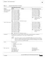
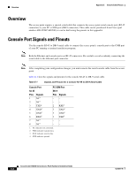
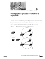
Overview Appendix E Console Cable Pinouts Overview The access point requires a special serial cable that connects the access point serial console port (RJ-45 connector) to your PC's COM port (DB-9 connector). This cable can be purchased from Cisco (part number AIR-CONCAB1200) or can be built using the pinouts in this appendix. Console Port Signals and Pinouts Use the console RJ-45 to DB-9 serial cable to connect the access point's console port to the COM port of your PC running a terminal emulation program. Note Both the Ethernet and console ports use RJ-45 connectors. Be careful to avoid accidently connecting the serial cable to the Ethernet port connector. Note After completing your configuration changes, you must remove the serial console cable from the access point. Table E-1 lists the signals and pinouts for the console RJ-45 to DB-9 serial cable. Table E-1 Signals and Pinouts for a Console RJ-45 to DB-9 Serial Cable Console Port PC COM Port RJ-45 DB-9 Pins Signals 1 NC1 2 NC1 3 TXD2 4 GND4 5 GND3 6 RXD5 7 NC1 8 NC1 Pins Signals -- -- 2 RXD3 5 GND4 5 GND4 3 TXD2 -- -- 1. NC indicates not connected. 2. TXD indicates transmit data. 3. RXD indicates receive data. 4. GND indicates ground Cisco Aironet 1240AG Series Access Point Hardware Installation Guide E-2 OL-8371-05
-
 1
1 -
2
-
3
-
4
-
5
-
6
-
7
-
8
-
9
-
10
-
11
-
12
-
13
-
14
-
15
-
16
-
17
-
18
-
19
-
20
-
21
-
22
-
23
-
24
-
25
-
26
-
27
-
28
-
29
-
30
-
31
-
32
-
33
-
34
-
35
-
36
-
37
-
38
-
39
-
40
-
41
-
42
-
43
-
44
-
45
-
46
-
47
-
48
-
49
-
50
-
51
-
52
-
53
-
54
-
55
-
56
-
57
-
58
-
59
-
60
-
61
-
62
-
63
-
64
-
65
-
66
-
67
-
68
-
69
-
70
-
71
-
72
-
73
-
74
-
75
-
76
-
77
-
78
-
79
-
80
-
81
-
82
-
83
-
84
-
85
-
86
-
87
-
88
-
89
-
90
-
91
-
92
-
93
-
94
-
95
-
96
-
97
-
98
-
99
-
100
-
 101
101 -
 102
102 -
 103
103 -
 104
104 -
 105
105 -
 106
106 -
 107
107 -
 108
108 -
 109
109 -
 110
110 -
 111
111 -
112
-
113
-
114
-
115
-
116
-
117
-
118
-
119
-
120
-
121
-
122
-
123
-
124
 |
 |