Cisco AIR-AP1242AG-A-K9 Hardware Installation Guide - Page 44
Attaching the Access Point to the Mounting Plate - protection
 |
UPC - 882658021961
View all Cisco AIR-AP1242AG-A-K9 manuals
Add to My Manuals
Save this manual to your list of manuals |
Page 44 highlights
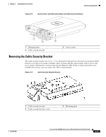
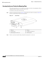
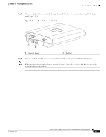
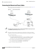
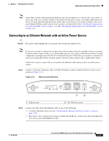
Attaching the Access Point to the Mounting Plate Chapter 2 Installing the Access Point To remove the cable security bracket from the mounting plate, follow these instructions: Step 1 Position the mounting plate with the cable security bracket pointing down (see Figure 2-9). Step 2 Remove the two screws that attach the bracket to the mounting plate using a phillips screw driver. Attaching the Access Point to the Mounting Plate Follow these steps to attach the access point to the mounting plate: Step 1 If your mounting plate has the cable security bracket, follow these steps: a. Connect the Ethernet cable to the access point Ethernet port (see the "Connecting the Ethernet and Power Cables" section on page 2-20). b. If not using on-line power, connect the power module's power cable to the access point 48-VDC connector. c. Carefully feed the Ethernet and power cables through the cable notch on the cable security bracket and slide the cables to the right or left to secure the cables (see the "Cable Security Bracket" section on page 2-14). Note If your access point is connected to Ethernet in-line power, do not connect the local power module to the access point. Using two power sources on the access point might cause the access point to shut down to protect internal components and might cause the switch to shut down the port to which the access point is connected. If your access point shuts down, you must remove all power and reconnect only a single power source. Step 2 Line up the four keyhole clips on the mounting plate with the large ends of the keyhole-shaped holes on the access point. Note The keyhole clips on each side of the mounting plate are offset and can only be positioned in one direction onto the access point. Step 3 Step 4 Step 5 Insert the mounting plate clips into the keyhole shaped holes on the access point. Slide the access point towards the cable security bracket end of the mounting bracket while exerting slight pressure to force the access point and mounting plate together. You will hear a slight click when the locking detents contact the access point and locks it into place. Attach and adjust the antenna(s) or antenna cables to the access point antenna connectors. Note The 5-GHz antennas and antenna cables have a blue dot or blue label. Connect only antennas or antenna cables with blue dots or labels to the access point's 5-GHz antenna connectors. 2-16 Cisco Aironet 1240AG Series Access Point Hardware Installation Guide OL-8371-05
-
 1
1 -
2
-
3
-
4
-
5
-
6
-
7
-
8
-
9
-
10
-
11
-
12
-
13
-
14
-
15
-
16
-
17
-
18
-
19
-
20
-
21
-
22
-
23
-
24
-
25
-
26
-
27
-
28
-
29
-
30
-
31
-
32
-
33
-
34
-
35
-
36
-
37
-
38
-
 39
39 -
 40
40 -
 41
41 -
 42
42 -
 43
43 -
 44
44 -
 45
45 -
 46
46 -
 47
47 -
 48
48 -
 49
49 -
50
-
51
-
52
-
53
-
54
-
55
-
56
-
57
-
58
-
59
-
60
-
61
-
62
-
63
-
64
-
65
-
66
-
67
-
68
-
69
-
70
-
71
-
72
-
73
-
74
-
75
-
76
-
77
-
78
-
79
-
80
-
81
-
82
-
83
-
84
-
85
-
86
-
87
-
88
-
89
-
90
-
91
-
92
-
93
-
94
-
95
-
96
-
97
-
98
-
99
-
100
-
101
-
102
-
103
-
104
-
105
-
106
-
107
-
108
-
109
-
110
-
111
-
112
-
113
-
114
-
115
-
116
-
117
-
118
-
119
-
120
-
121
-
122
-
123
-
124
 |
 |