Cisco AIR-AP1242AG-A-K9 Hardware Installation Guide - Page 50
Connecting to an Ethernet Network with Local Power, Powering Up the Access Point - status lights
 |
UPC - 882658021961
View all Cisco AIR-AP1242AG-A-K9 manuals
Add to My Manuals
Save this manual to your list of manuals |
Page 50 highlights
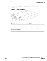
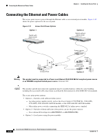
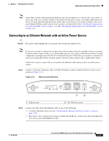
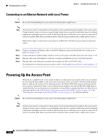
Powering Up the Access Point Chapter 2 Installing the Access Point Connecting to an Ethernet Network with Local Power Caution Be careful when handling the access point; the bottom plate might be hot. Note If your access point is connected to in-line power, do not connect the power module to the access point. Using two power sources on the access point might cause the access point to shut down to protect internal components and might cause the switch to shut down the port to which the access point is connected. If your access point shuts down, you must remove all power and reconnect only a single power source. Follow these steps to connect the access point to an Ethernet LAN when you are using a local power source: Step 1 Step 2 Step 3 Step 4 Connect a Category 5 Ethernet cable to the RJ-45 Ethernet connector labeled Ethernet on the access point (see Figure 2-13). Connect the power module output connector to the access point's 48-VDC power port (see Figure 2-13). Plug the other end of the Ethernet cable into an unpowered Ethernet port on your LAN network. Plug the other end of the power module into an approved 100- to 240-VAC outlet. For information on securing your access point, see the "Securing the Access Point" section on page 2-17. Powering Up the Access Point When power is applied to the access point, it begins a routine power-up sequence that you can monitor by observing the three LEDs on the end of the access point. After you observe all three LEDs turning green to indicate the starting of the operating system, the Status LED blinks green signifying that the access point is operational. After a successful power-up sequence, the Status LED turns light green to signify that there are no client devices associated, or it turns blue to signify that there are client devices associated. Refer to the "Checking the Autonomous Access Point LEDs" section on page 3-2 or the "Checking the Lightweight Access Point LEDs" section on page 4-3 for LED descriptions. Caution Be careful when handling the access point; the bottom plate might be hot. Note If your access point is connected to in-line power, do not connect the power module to the access point. Using two power sources on the access point might cause the access point to shut down to protect internal components and might cause the switch to shut down the port to which the access point is connected. If your access point shuts down, you must remove all power and reconnect only a single power source. 2-22 Cisco Aironet 1240AG Series Access Point Hardware Installation Guide OL-8371-05
-
 1
1 -
2
-
3
-
4
-
5
-
6
-
7
-
8
-
9
-
10
-
11
-
12
-
13
-
14
-
15
-
16
-
17
-
18
-
19
-
20
-
21
-
22
-
23
-
24
-
25
-
26
-
27
-
28
-
29
-
30
-
31
-
32
-
33
-
34
-
35
-
36
-
37
-
38
-
39
-
40
-
41
-
42
-
43
-
44
-
 45
45 -
 46
46 -
 47
47 -
 48
48 -
 49
49 -
 50
50 -
 51
51 -
 52
52 -
 53
53 -
 54
54 -
 55
55 -
56
-
57
-
58
-
59
-
60
-
61
-
62
-
63
-
64
-
65
-
66
-
67
-
68
-
69
-
70
-
71
-
72
-
73
-
74
-
75
-
76
-
77
-
78
-
79
-
80
-
81
-
82
-
83
-
84
-
85
-
86
-
87
-
88
-
89
-
90
-
91
-
92
-
93
-
94
-
95
-
96
-
97
-
98
-
99
-
100
-
101
-
102
-
103
-
104
-
105
-
106
-
107
-
108
-
109
-
110
-
111
-
112
-
113
-
114
-
115
-
116
-
117
-
118
-
119
-
120
-
121
-
122
-
123
-
124
 |
 |