Cisco AIR-AP1242AG-A-K9 Hardware Installation Guide - Page 56
Intelligent Power Management, Inline Power Status Messages
 |
UPC - 882658021961
View all Cisco AIR-AP1242AG-A-K9 manuals
Add to My Manuals
Save this manual to your list of manuals |
Page 56 highlights
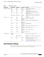
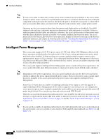
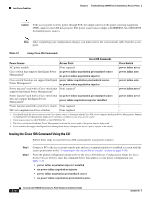
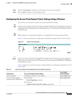
Low Power Condition Chapter 3 Troubleshooting 1240AG Series Autonomous Access Points Note If your access point is connected to in-line power, do not connect the power module to the access point. Using two power sources on the access point might cause the access point to shut down to protect internal components and might cause the switch to shut down the port to which the access point is connected. If your access point shuts down, you must remove all power and reconnect only a single power source. On power up, the access point is placed into low power mode (both radios are disabled), Cisco IOS software loads and runs, and power negotiation determines if sufficient power is available. If there is sufficient power then the radios are turned on; otherwise, the access point remains in low power mode with the radios disabled to prevent a possible over-current condition. In low power mode, the access point activates the Status LED low power error indication, displays a low power message on the browser and serial interfaces, and creates an event log entry (see the "Checking the Autonomous Access Point LEDs" section on page 3-2 and "Inline Power Status Messages" section on page 3-7). Intelligent Power Management The access point requires 12.95 W of power (up to 15.4 W with 100 m CAT 5 Ethernet cable) for full power operation with both radios, but only needs 6.3 W of power when operating in low power mode with both radios disabled. To help avoid an over-current condition with low power sources and to optimize power usage on Cisco switches, Cisco developed Intelligent Power Management, which uses Cisco Discovery Protocol (CDP) to allow powered devices (such as your access point) to negotiate with a Cisco switch for sufficient power. The access point supports Intelligent Power Management and as a result of the power negotiations, the access point will either enter full power mode or remain in low power mode with the radios disabled. Note Independent of the power negotiations, the access point hardware also uses the 802.3af classification scheme to indicate the power required from the power source. However, the power source cannot report the power available to the access point unless the power source also supports Intelligent Power Management. Some Cisco switches that are capable of supplying sufficient power require a software upgrade to support Intelligent Power Management. If the software upgrade is not desired, you can configure the access point to operate in pre-standard compatibility mode and the access point automatically enters full power mode if these Cisco switches are detected in the received CDP ID field. When the access point determines that sufficient power is not available for full power operation, an error message is logged and the Status LED turns amber to indicate low power mode (see the "Checking the Autonomous Access Point LEDs" section on page 3-2 and the "Inline Power Status Messages" section on page 3-7). Tip If your switch is capable of supplying sufficient power for full operation but the access point remains in low-power mode, your access point or your switch (or both) might be misconfigured (see Table 3-2 and Table 3-3). Cisco Aironet 1240AG Series Access Point Hardware Installation Guide 3-6 OL-8371-05
-
 1
1 -
2
-
3
-
4
-
5
-
6
-
7
-
8
-
9
-
10
-
11
-
12
-
13
-
14
-
15
-
16
-
17
-
18
-
19
-
20
-
21
-
22
-
23
-
24
-
25
-
26
-
27
-
28
-
29
-
30
-
31
-
32
-
33
-
34
-
35
-
36
-
37
-
38
-
39
-
40
-
41
-
42
-
43
-
44
-
45
-
46
-
47
-
48
-
49
-
50
-
 51
51 -
 52
52 -
 53
53 -
 54
54 -
 55
55 -
 56
56 -
 57
57 -
 58
58 -
 59
59 -
 60
60 -
 61
61 -
62
-
63
-
64
-
65
-
66
-
67
-
68
-
69
-
70
-
71
-
72
-
73
-
74
-
75
-
76
-
77
-
78
-
79
-
80
-
81
-
82
-
83
-
84
-
85
-
86
-
87
-
88
-
89
-
90
-
91
-
92
-
93
-
94
-
95
-
96
-
97
-
98
-
99
-
100
-
101
-
102
-
103
-
104
-
105
-
106
-
107
-
108
-
109
-
110
-
111
-
112
-
113
-
114
-
115
-
116
-
117
-
118
-
119
-
120
-
121
-
122
-
123
-
124
 |
 |