Cisco AIR-AP1242AG-A-K9 Hardware Installation Guide - Page 74
Message type, Ethernet LED, Radio LED, Status LED, Meaning, No Cisco IOS image file.
 |
UPC - 882658021961
View all Cisco AIR-AP1242AG-A-K9 manuals
Add to My Manuals
Save this manual to your list of manuals |
Page 74 highlights
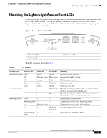
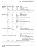
Checking the Lightweight Access Point LEDs Chapter 4 Troubleshooting 1240AG Series Lightweight Access Points Table 4-1 LED Signals (continued) Message type Ethernet LED Radio LED Status LED Meaning Boot loader Off Off Yellow Ethernet link not operational. warnings Red Off Yellow Ethernet failure. Amber Off Yellow Configuration recovery in progress (Mode button pressed for 2 to 3 seconds). Off Red Pink Image recovery (Mode button pressed for 20 to 30 seconds) Blinking green Blinking red Blinking pink Image recovery in progress and Mode button is released. Boot loader errors Red Red Red DRAM memory test failure. Off Red Blinking red Flash file system failure. and blue Off Amber Blinking red Environment variable (ENVAR) failure. and blue-green Amber Off Blinking red Bad MAC address. and yellow Red Off Blinking red Ethernet failure during image recovery. and off Amber Amber Blinking red Boot environment error. and off Red Amber Blinking red No Cisco IOS image file. and off Amber Amber Blinking red Boot failure. and off Cisco IOS errors Blinking amber - - Transmit or receive Ethernet errors. - Blinking - Maximum retries or buffer full occurred on the radio. amber Red Red Amber Software failure; try disconnecting and reconnecting unit power. - - Amber Controller status Alternating green, red , and amber1 General warning, insufficient inline power (see the Low Power Condition for Lightweight Access Points section). Connecting to the controller. Note If the access point remains in this mode for more than five minutes, the access point is unable to find the controller. Ensure a DHCP server is available or that controller information is configured on the access point. Green Green Blinking dark Loading the access point image file. blue 1. This status indication has the highest priority and overrides other status indications. Cisco Aironet 1240AG Series Access Point Hardware Installation Guide 4-4 OL-8371-05
-
 1
1 -
2
-
3
-
4
-
5
-
6
-
7
-
8
-
9
-
10
-
11
-
12
-
13
-
14
-
15
-
16
-
17
-
18
-
19
-
20
-
21
-
22
-
23
-
24
-
25
-
26
-
27
-
28
-
29
-
30
-
31
-
32
-
33
-
34
-
35
-
36
-
37
-
38
-
39
-
40
-
41
-
42
-
43
-
44
-
45
-
46
-
47
-
48
-
49
-
50
-
51
-
52
-
53
-
54
-
55
-
56
-
57
-
58
-
59
-
60
-
61
-
62
-
63
-
64
-
65
-
66
-
67
-
68
-
 69
69 -
 70
70 -
 71
71 -
 72
72 -
 73
73 -
 74
74 -
 75
75 -
 76
76 -
 77
77 -
 78
78 -
 79
79 -
80
-
81
-
82
-
83
-
84
-
85
-
86
-
87
-
88
-
89
-
90
-
91
-
92
-
93
-
94
-
95
-
96
-
97
-
98
-
99
-
100
-
101
-
102
-
103
-
104
-
105
-
106
-
107
-
108
-
109
-
110
-
111
-
112
-
113
-
114
-
115
-
116
-
117
-
118
-
119
-
120
-
121
-
122
-
123
-
124
 |
 |