Cisco AIR-AP1242AG-E-K9 Hardware Installation Guide - Page 21
LEDs, Ethernet Port, The Ethernet LED signals Ethernet traffic on the wired LAN - power injector
 |
View all Cisco AIR-AP1242AG-E-K9 manuals
Add to My Manuals
Save this manual to your list of manuals |
Page 21 highlights
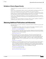
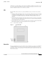
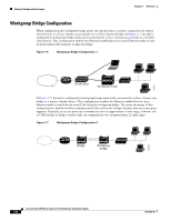
Chapter 1 Overview Hardware Features LEDs (5805 GHz). To avoid this problem, set the channel on the RM21A or RM22A radio module to one of the channels supported by the CB20A client radio. For additional information, refer to the Cisco IOS Software Configuration Guide for Cisco Aironet Access Points. The three LEDs on the top of the access point report Ethernet activity, association status, and radio activity. • The Ethernet LED signals Ethernet traffic on the wired LAN, or Ethernet infrastructure. This LED is normally green when an Ethernet cable is connected and blinks green when a packet is received or transmitted over the Ethernet infrastructure. The LED is off when the Ethernet cable is not connected. • The status LED signals operational status. Green indicates that the access point is associated with at least one wireless client. Blinking green indicates that the access point is operating normally but is not associated with any wireless devices. • The radio LED signals wireless traffic over the radio interface. The light is normally off, but it blinks green whenever a packet is received or transmitted over the access point radio. Figure 1-1 shows the three status LEDs. Figure 1-1 Access Point LEDs Ethernet Status Radio 86704 Ethernet Port The auto-sensing Ethernet port accepts an RJ-45 connector, linking the access point to your 10BASE-T or 100BASE-T Ethernet LAN. The access point can receive power through the Ethernet cable from a power injector, switch, or power patch panel. The Ethernet MAC address is printed on the label on the back of the access point. OL-4310-05 Cisco Aironet 1200 Series Access Point Hardware Installation Guide 1-3
-
 1
1 -
2
-
3
-
4
-
5
-
6
-
7
-
8
-
9
-
10
-
11
-
12
-
13
-
14
-
15
-
 16
16 -
 17
17 -
 18
18 -
 19
19 -
 20
20 -
 21
21 -
 22
22 -
 23
23 -
 24
24 -
 25
25 -
 26
26 -
27
-
28
-
29
-
30
-
31
-
32
-
33
-
34
-
35
-
36
-
37
-
38
-
39
-
40
-
41
-
42
-
43
-
44
-
45
-
46
-
47
-
48
-
49
-
50
-
51
-
52
-
53
-
54
-
55
-
56
-
57
-
58
-
59
-
60
-
61
-
62
-
63
-
64
-
65
-
66
-
67
-
68
-
69
-
70
-
71
-
72
-
73
-
74
-
75
-
76
-
77
-
78
-
79
-
80
-
81
-
82
-
83
-
84
-
85
-
86
-
87
-
88
-
89
-
90
-
91
-
92
-
93
-
94
-
95
-
96
-
97
-
98
-
99
-
100
-
101
-
102
-
103
-
104
-
105
-
106
-
107
-
108
-
109
-
110
-
111
-
112
-
113
-
114
-
115
-
116
-
117
-
118
-
119
-
120
-
121
-
122
-
123
-
124
-
125
-
126
-
127
-
128
-
129
-
130
-
131
-
132
-
133
-
134
-
135
-
136
-
137
-
138
-
139
-
140
-
141
-
142
-
143
-
144
-
145
-
146
-
147
-
148
-
149
-
150
-
151
-
152
-
153
-
154
-
155
-
156
-
157
-
158
-
159
-
160
 |
 |