Cisco AIR-AP1242AG-E-K9 Hardware Installation Guide - Page 30
Installation Above Suspended Ceilings, Before Beginning the Installation
 |
View all Cisco AIR-AP1242AG-E-K9 manuals
Add to My Manuals
Save this manual to your list of manuals |
Page 30 highlights
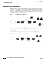
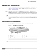
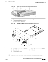
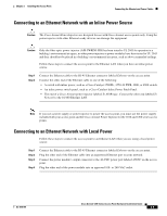
Before Beginning the Installation Chapter 2 Installing the Access Point Installation Above Suspended Ceilings The access point uses a metal enclosure having adequate fire resistance and low smoke-producing characteristics suitable for operation in a building's environmental air space (such as above suspended ceilings) in accordance with Section 300-22(c) of the NEC. For mounting instructions, refer to the Chapter 6, "Mounting Instructions." Caution Only the fiber-optic power injector (AIR-PWRINJ-FIB) has been tested to UL 2043 for operation in a building's environmental air space; no other power injectors or power modules have been tested to UL 2043 and they should not be placed in a building's environmental air space, such as above suspended ceilings. Note If you plan to mount the access point with a 5-GHz radio in environmental air space, Cisco recommends that you mount the access point horizontally with its antennas pointing down. Doing so will result in the access point complying with regulatory requirements for environmental air space with the 5-GHz radio installed. Before Beginning the Installation Before you begin the installation process, please refer to Figure 2-1, Figure 2-2, and Figure 2-3 to become familiar with the access point's layout, connectors, and 5-GHz module location. Figure 2-1 Access Point Layout and Connectors 1 234 5 6 65847 7 1 1 2.4-GHz antenna connectors 2 48-VDC power port 3 Ethernet port (RJ-45) 4 Console port (RJ-45) 5 Mode button 6 Status LEDs 7 Mounting bracket Note Do not connect Cisco 5-GHz antennas with blue labels or blue dots to the 2.4-GHz antenna connectors. Cisco Aironet 1200 Series Access Point Hardware Installation Guide 2-4 OL-4310-05
-
 1
1 -
2
-
3
-
4
-
5
-
6
-
7
-
8
-
9
-
10
-
11
-
12
-
13
-
14
-
15
-
16
-
17
-
18
-
19
-
20
-
21
-
22
-
23
-
24
-
 25
25 -
 26
26 -
 27
27 -
 28
28 -
 29
29 -
 30
30 -
 31
31 -
 32
32 -
 33
33 -
 34
34 -
 35
35 -
36
-
37
-
38
-
39
-
40
-
41
-
42
-
43
-
44
-
45
-
46
-
47
-
48
-
49
-
50
-
51
-
52
-
53
-
54
-
55
-
56
-
57
-
58
-
59
-
60
-
61
-
62
-
63
-
64
-
65
-
66
-
67
-
68
-
69
-
70
-
71
-
72
-
73
-
74
-
75
-
76
-
77
-
78
-
79
-
80
-
81
-
82
-
83
-
84
-
85
-
86
-
87
-
88
-
89
-
90
-
91
-
92
-
93
-
94
-
95
-
96
-
97
-
98
-
99
-
100
-
101
-
102
-
103
-
104
-
105
-
106
-
107
-
108
-
109
-
110
-
111
-
112
-
113
-
114
-
115
-
116
-
117
-
118
-
119
-
120
-
121
-
122
-
123
-
124
-
125
-
126
-
127
-
128
-
129
-
130
-
131
-
132
-
133
-
134
-
135
-
136
-
137
-
138
-
139
-
140
-
141
-
142
-
143
-
144
-
145
-
146
-
147
-
148
-
149
-
150
-
151
-
152
-
153
-
154
-
155
-
156
-
157
-
158
-
159
-
160
 |
 |