Cisco AIR-AP1242AG-E-K9 Hardware Installation Guide - Page 35
Connecting to an Ethernet Network with an Inline Power Source, Connecting to an Ethernet Network
 |
View all Cisco AIR-AP1242AG-E-K9 manuals
Add to My Manuals
Save this manual to your list of manuals |
Page 35 highlights
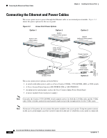
Chapter 2 Installing the Access Point Connecting the Ethernet and Power Cables Connecting to an Ethernet Network with an Inline Power Source Caution The Cisco Aironet Power Injectors are designed for use with Cisco Aironet access points only. Using the power injector with other Ethernet-ready devices can damage the equipment. Caution Only the fiber-optic power injector (AIR-PWRINJ-FIB) has been tested to UL 2043 for operation in a building's environmental air space; no other power injectors or power modules have been tested to UL 2043 and they should not be placed in a building's environmental air space, such as above suspended ceilings. Follow these steps to connect the access point to the Ethernet LAN when you have an inline power source: Step 1 Step 2 Connect the Ethernet cable to the RJ-45 Ethernet connector labeled Ethernet on the access point. Connect the other end of the Ethernet cable to one of the following: • A switch with inline power, such as a Cisco Catalyst 3500XL, 3550-24 PWR, 4000, or 6500 switch. • An inline power switch panel, such as a Cisco Catalyst Inline Power Patch Panel. • The end of a Cisco Aironet power injector labeled To AP/Bridge. Connect the other end labeled To Network to the 10/100 Ethernet LAN. Note If you use a power supply or power injector to power the access point, you must use the power supply included with your access point and the Cisco Aironet Power Injector for the 1100 and 1200 series access points. Connecting to an Ethernet Network with Local Power Follow these steps to connect the access point to an Ethernet LAN when you are using a local power source: Step 1 Step 2 Step 3 Step 4 Connect the Ethernet cable to the RJ-45 Ethernet connector labeled Ethernet on the access point. Plug the other end of the Ethernet cable into an unpowered Ethernet port on your network. Connect the power module's output connector to the 48-VDC power port labeled 48VDC on the access point. Plug the other end of the power module into an approved 100- to 240-VAC outlet. OL-4310-05 Cisco Aironet 1200 Series Access Point Hardware Installation Guide 2-9
-
 1
1 -
2
-
3
-
4
-
5
-
6
-
7
-
8
-
9
-
10
-
11
-
12
-
13
-
14
-
15
-
16
-
17
-
18
-
19
-
20
-
21
-
22
-
23
-
24
-
25
-
26
-
27
-
28
-
29
-
 30
30 -
 31
31 -
 32
32 -
 33
33 -
 34
34 -
 35
35 -
 36
36 -
 37
37 -
 38
38 -
 39
39 -
 40
40 -
41
-
42
-
43
-
44
-
45
-
46
-
47
-
48
-
49
-
50
-
51
-
52
-
53
-
54
-
55
-
56
-
57
-
58
-
59
-
60
-
61
-
62
-
63
-
64
-
65
-
66
-
67
-
68
-
69
-
70
-
71
-
72
-
73
-
74
-
75
-
76
-
77
-
78
-
79
-
80
-
81
-
82
-
83
-
84
-
85
-
86
-
87
-
88
-
89
-
90
-
91
-
92
-
93
-
94
-
95
-
96
-
97
-
98
-
99
-
100
-
101
-
102
-
103
-
104
-
105
-
106
-
107
-
108
-
109
-
110
-
111
-
112
-
113
-
114
-
115
-
116
-
117
-
118
-
119
-
120
-
121
-
122
-
123
-
124
-
125
-
126
-
127
-
128
-
129
-
130
-
131
-
132
-
133
-
134
-
135
-
136
-
137
-
138
-
139
-
140
-
141
-
142
-
143
-
144
-
145
-
146
-
147
-
148
-
149
-
150
-
151
-
152
-
153
-
154
-
155
-
156
-
157
-
158
-
159
-
160
 |
 |