Cisco AIR-AP1242AG-E-K9 Hardware Installation Guide - Page 68
Mounting Bracket, Cisco Aironet 1200 Series Access Point Hardware Installation Guide
 |
View all Cisco AIR-AP1242AG-E-K9 manuals
Add to My Manuals
Save this manual to your list of manuals |
Page 68 highlights
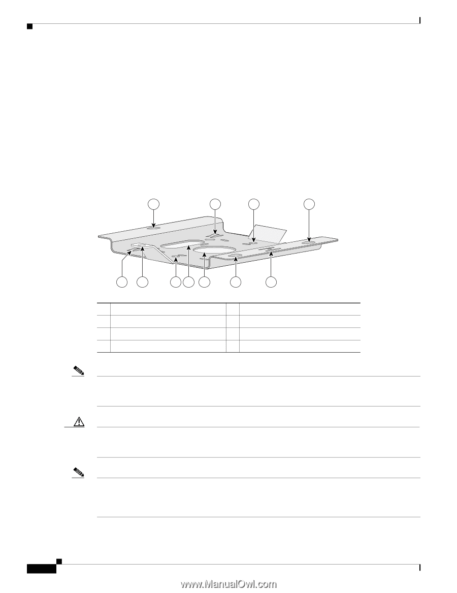
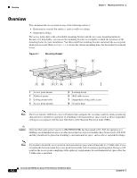
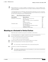
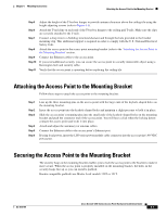
Overview Chapter 6 Mounting Instructions Overview You can mount the access point on any of the following surfaces: • Horizontal or vertical flat surfaces, such as walls or ceilings • Suspended ceilings The access point ships with a detachable mounting bracket and the necessary mounting hardware. Because it is detachable, you can use the mounting bracket as a template to mark the positions of the mounting holes for your installation. You then install the mounting bracket and attach the access point when you are ready. Refer to Figure 6-1 to locate the various mounting holes for the method you intend to use. Figure 6-1 Mounting Bracket 1 2 3 4 65863 28 37 6 4 5 1 Access point mount 2 Cable tie points 3 Ceiling mount holes 4 Access point mounts 5 Locking detent 6 Wall cable access 7 Suspended ceiling cable access 8 Security hasp Note The Cisco Aironet 1200 Series Access Point provides adequate fire resistance and low smoke-producing characteristics suitable for operation in a building's environmental air space (such as above suspended ceilings) in accordance with Section 300-22(C) of the National Electrical Code (NEC). Caution Only the fiber-optic power injector (AIR-PWRINJ-FIB) has been tested to UL 2043 for operation in a building's environmental air space; no other power injectors or power modules have been tested to UL 2043 and they should not be placed in a building's environmental air space, such as above suspended ceilings. Note If you plan to mount the access point in environmental air space and will upgrade to a 5-GHz radio, Cisco recommends that you mount the access point horizontally with its antennas pointing down. Doing so will result in the access point complying with regulatory requirements for environmental air space after the 5-GHz radio is installed. Cisco Aironet 1200 Series Access Point Hardware Installation Guide 6-2 OL-4310-05
-
 1
1 -
2
-
3
-
4
-
5
-
6
-
7
-
8
-
9
-
10
-
11
-
12
-
13
-
14
-
15
-
16
-
17
-
18
-
19
-
20
-
21
-
22
-
23
-
24
-
25
-
26
-
27
-
28
-
29
-
30
-
31
-
32
-
33
-
34
-
35
-
36
-
37
-
38
-
39
-
40
-
41
-
42
-
43
-
44
-
45
-
46
-
47
-
48
-
49
-
50
-
51
-
52
-
53
-
54
-
55
-
56
-
57
-
58
-
59
-
60
-
61
-
62
-
 63
63 -
 64
64 -
 65
65 -
 66
66 -
 67
67 -
 68
68 -
 69
69 -
 70
70 -
 71
71 -
 72
72 -
 73
73 -
74
-
75
-
76
-
77
-
78
-
79
-
80
-
81
-
82
-
83
-
84
-
85
-
86
-
87
-
88
-
89
-
90
-
91
-
92
-
93
-
94
-
95
-
96
-
97
-
98
-
99
-
100
-
101
-
102
-
103
-
104
-
105
-
106
-
107
-
108
-
109
-
110
-
111
-
112
-
113
-
114
-
115
-
116
-
117
-
118
-
119
-
120
-
121
-
122
-
123
-
124
-
125
-
126
-
127
-
128
-
129
-
130
-
131
-
132
-
133
-
134
-
135
-
136
-
137
-
138
-
139
-
140
-
141
-
142
-
143
-
144
-
145
-
146
-
147
-
148
-
149
-
150
-
151
-
152
-
153
-
154
-
155
-
156
-
157
-
158
-
159
-
160
 |
 |