Cisco AIR-AP1242AG-E-K9 Hardware Installation Guide - Page 69
Mounting on a Horizontal or Vertical Surface
 |
View all Cisco AIR-AP1242AG-E-K9 manuals
Add to My Manuals
Save this manual to your list of manuals |
Page 69 highlights
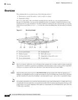
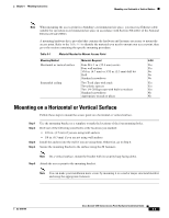
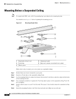
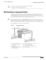
Chapter 6 Mounting Instructions Mounting on a Horizontal or Vertical Surface Note When mounting the access point in a building's environmental air space, you must use Ethernet cable suitable for operation in environmental air space in accordance with Section 300-22(C) of the National Electrical Code (NEC). A mounting hardware kit is provided that contains the hardware and fasteners necessary to mount the access point. Refer to the Table 6-1 to identify the materials you need to mount your access point, then go to the section containing the specific mounting procedure. Table 6-1 Material Needed to Mount Access Point Mounting Method Materials Required In Kit Horizontal or vertical surface Four #8 x 1 in. (25.4 mm) screws Yes Four wall anchors Yes 3/16 in. (4.7 mm) or 3/32 in. (2.3 mm) drill bit No Drill No Standard screwdriver No Suspended ceiling Two T-rail clips with studs Yes Two plastic spacers Yes Two 1/4-20 Keps nuts with built-in washers Yes Standard screwdriver No Appropriate wrench or pliers No Mounting on a Horizontal or Vertical Surface Follow these steps to mount the access point on a horizontal or vertical surface. Step 1 Step 2 Step 3 Step 4 Use the mounting bracket as a template to mark the locations of the four mounting holes. Drill one of the following sized holes at the locations you marked: • 3/16 in. (4.7 mm) if you are using wall anchors • 1/8 in. (6.3 mm) if you are not using wall anchors Install the anchors into the wall if you are using them. Otherwise, go to Step 4. Secure the mounting bracket to the surface using the #8 fasteners. Note On a vertical surface, mount the bracket with its security hasp facing down. Step 5 Attach the access point to the mounting bracket. Note You can make your installation more secure by mounting it to a stud or major structural member and using the appropriate fasteners. OL-4310-05 Cisco Aironet 1200 Series Access Point Hardware Installation Guide 6-3
-
 1
1 -
2
-
3
-
4
-
5
-
6
-
7
-
8
-
9
-
10
-
11
-
12
-
13
-
14
-
15
-
16
-
17
-
18
-
19
-
20
-
21
-
22
-
23
-
24
-
25
-
26
-
27
-
28
-
29
-
30
-
31
-
32
-
33
-
34
-
35
-
36
-
37
-
38
-
39
-
40
-
41
-
42
-
43
-
44
-
45
-
46
-
47
-
48
-
49
-
50
-
51
-
52
-
53
-
54
-
55
-
56
-
57
-
58
-
59
-
60
-
61
-
62
-
63
-
 64
64 -
 65
65 -
 66
66 -
 67
67 -
 68
68 -
 69
69 -
 70
70 -
 71
71 -
 72
72 -
 73
73 -
 74
74 -
75
-
76
-
77
-
78
-
79
-
80
-
81
-
82
-
83
-
84
-
85
-
86
-
87
-
88
-
89
-
90
-
91
-
92
-
93
-
94
-
95
-
96
-
97
-
98
-
99
-
100
-
101
-
102
-
103
-
104
-
105
-
106
-
107
-
108
-
109
-
110
-
111
-
112
-
113
-
114
-
115
-
116
-
117
-
118
-
119
-
120
-
121
-
122
-
123
-
124
-
125
-
126
-
127
-
128
-
129
-
130
-
131
-
132
-
133
-
134
-
135
-
136
-
137
-
138
-
139
-
140
-
141
-
142
-
143
-
144
-
145
-
146
-
147
-
148
-
149
-
150
-
151
-
152
-
153
-
154
-
155
-
156
-
157
-
158
-
159
-
160
 |
 |